6-2-2-p0723-0782-cxsj_en.pdf - 第40页
Operating Environment Speed Adjustment CXS Series Specific Product Precautions Be sure to read this before handling the products. Refer to back page 50 for Safety Instructions and pages 3 to 12 for Actuator and Auto Swit…
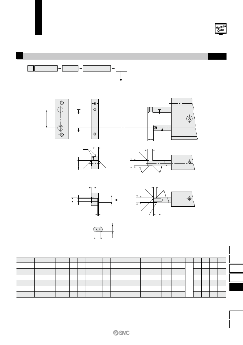
Without Plate
1
This specification is for the cylinder without a plate. This cylinder is suitable for mounting your own plate.
Please note that the rod end dimensions of this cylinder are different from those of the standard cylinder.
CXS X593
Bore size
Without plate
Stroke Auto switch
B
A A
B
C
O
View C
Section A-A
Section B-B
C
a
s
b
d
e
f g
C0.2
C0.2
C0.5
45
°
45°
i
h
L1
k
m
45
°
p
n
(d)
q
C0.5
C0.5
t
j
r
(L1)
a
16
±
0.1
20
±
0.1
25
±
0.1
28
±
0.1
35
±
0.1
44
±
0.1
b
ø4
ø6
ø8
ø10
ø12
ø16
+0.019
+0.001
+0.019
+0.001
c
M3 x 0.5
M5 x 0.8
M6 x 1.0
M8 x 1.25
M8 x 1.25
M10 x 1.5
d
ø4
ø6
ø8
ø10
ø12
ø16
e
ø3.5
ø5.5
ø7.5
ø9.5
ø11.5
ø15.5
f
1
1.25
2
2
2
3.5
g
3
4.5
5
7
7
8
j
2.75
4
5
6
6
8
h
ø5.5
ø6.5
ø9.5
ø11
ø11
ø14
i o
M2.5 x 0.45
M3 x 0.5
M5 x 0.8
M6 x 1.0
M6 x 1.0
M8 x 1.25
q
4.5
8
8
10
12
12.5
p
3
r
3.5
5
7
8
8.5
11
s
4.75
6.5
8
9.5
9.5
13.5
ø6
ø3.5
ø5.5
ø6.6
ø6.6
ø9
0
–0.2
0
–0.2
0
–0.2
0
–0.2
0
–0.2
0
–0.2
k
2.8
3.2
5.2
6.2
6.2
8.2
+0.2
0
+0.2
0
+0.3
0
+0.3
0
+0.3
0
+0.4
0
n
3.5
5
6
8
10
13
–0.05
–0.15
–0.05
–0.15
–0.05
–0.15
–0.05
–0.15
–0.05
–0.15
–0.05
–0.15
m
0.5
1
1.5
2
2
2
+0.2
0
+0.2
0
+0.2
0
+0.2
0
+0.2
0
+0.2
0
L1
3.5
5
6
8
10
13
+0.1
0
+0.1
0
+0.2
0
+0.2
0
+0.2
0
+0.2
0
Model
CXS10
CXS
6
CXS
15
CXS
20
CXS
25
CXS
32
+0.016
+0.001
+0.013
+0.001
+0.016
+0.001
+0.016
+0.001
t
C0.5
C0.5
C0.5
C0.5
C0.7
C0.7
(mm)
-X593
Symbol
Note 1) Unless indicated otherwise, the dimensional tolerance conforms to the ordinary dimensional difference (matching) per JIS B 0405.
Note 2) Piston rod A and B must be extended in order to install a plate. Apply presure (0.2 MPa or more) from the supply port of the extended end when installing a plate.
To secure the plate to the rods, attach it first to piston rod B, and then to piston rod A. Make sure to apply Loctite to the threaded portion.
After anchoring the plate, operate the cylinder to check for proper operation (e.g., the cylinder operates smoothly when moved by hand or at least operates properly at the
minimum operating pressure).
CXS Series
Made to Order: Individual Specifications
Please contact SMC for detailed dimensions, specifications and lead times.
759
CX2
CXW
CXT
CXSJ
CXS
D-
-X
CXS
Operating Environment
Speed Adjustment
CXS Series
Specific Product Precautions
Be sure to read this before handling the products.
Refer to back page 50 for Safety Instructions and pages 3 to 12 for Actuator and
Auto Switch Precautions.
Mounting
Caution
Caution
Caution
1. Make sure that the surface on which the cylinder is
to be mounted is flat (reference value for flatness:
0.05 or less).
Dual rod cylinders can be mounted from 3 directions,
however, make sure that the surface on which the cylinder is
to be mounted is flat (reference value for flatness: 0.05 or
less). Otherwise, the accuracy of the piston rod operation is
not achieved, and malfunctioning can occur.
2. Piston rod must be retracted when mounting the
cylinder.
Scratches or gouges in the piston rod may lead to damaged
bearings and seals and cause malfunctions or air leakage.
Caution
Caution
Caution
1. After adjusting the stroke, make sure to tighten the
hexagon nut to prevent it from loosening.
Dual rod cylinders have a bolt to adjust 0 to –5 mm strokes on
the retracted end (IN).
Loosen the hexagon nut to adjust the stroke; however, make
sure to tighten the hexagon nut after making an adjustment.
2.
Never operate a cylinder with its bumper bolt removed.
Also, do not attempt to tighten the bumper bolt
without using a nut.
If the bumper bolt is removed, the piston hits the head cover
causing damage to the cylinder. Therefore, do not use a
cylinder without a bumper bolt.
Furthermore, if the bumper bolt is tightened without a nut, the
piston seal is caught in the leveled part, damaging the seal.
Stroke Adjustment
Stroke Adjustment
3.
A bumper at the end of the bumper bolt is replaceable.
In case a missing bumper, or a bumper has a permanent
settling, use following part numbers for ordering.
Bore size (mm)
Part no.
Qty.
6, 10, 15
CXS10-34A
28747
20, 25
CXS20-34A
28749
1
32
CXS32-34A
28751
Disassembly and Maintenance
1. Never use a cylinder with its plate removed.
When removing the hexagon socket head cap screw on the
end plate, the piston rod must be secured to prevent from
rotating. However, if the sliding parts of the piston rod are
scratched and gouged, a malfunction may occur. If the plate is
not required for your application, use the cylinder that does not
come with a plate, available through made-to-order (-X593) on
page 759.
2. When disassembling and reassembling the cylinder,
please contact SMC or refer to the separate operation
manual.
1.
Do not operate the cylinder in a pressurized environment.
The pressurized air may flow inside the cylinder due to its
construction.
2.
Do not use as a stopper. This may cause malfunction.
When using as a stopper, select a stopper cylinder
(RS series) or a compact guide cylinder (MGP series).
1. A sudden extension may occur with CXS6.
CXS6 has a low internal volume and sudden extension/erratic
movement may occur particularly when it is used at low speed.
This sudden extension can be mitigated by combining the use
of meter-in and meter-out speed controllers.
Warning
1. Take precautions when your hands are near the
plate and housing.
Take sufficient care to avoid getting your hands or fingers
caught when the cylinder is operated.
Caution
1. Plug the appropriate supply port(s) according to the
operating conditions.
Dual-rod cylinders have 2 supply ports for each operating
direction (3 supply ports for ø6 only). Plug the appropriate
supply port according to the operating conditions. When
changing the port position, use the removed plug or a new
plug. If reusing the removed plug, apply sealant, etc., before
reassembly. If using a new M5 plug, apply a thin layer of
grease all the way around the male thread before use. In
addition, clear any foreign matter adhered to the port the plug
was removed from before piping.
After reassembly, be sure to check for air leakage before
operating the product.
Piping
(ø6)CXS10-08-28747B
(ø10 to ø20)CXS20-08-28749A
(ø25 to ø32)CYP025-08B29449(Rc 1/8)
CXS25-08-A3025A(NPT 1/8)
CXS25-08-A3911(G 1/8)
Plug part no.:
760
c
When operating an actuator with a small diameter
and a short stroke at a high frequency, the dew
condensation (water droplet) may occur inside the
piping depending on the conditions.
Simply connecting the moisture control tube to the
actuator will prevent dew condensation from oc-
curring. For details, refer to the IDK series in the
Best Pneumatics No. 6.
Moisture
Control Tube
IDK Series
CXS M 100 A20
M
L
Dual Rod Cylinder
Number of auto switches
(No. of auto switch)
Y7BW
Applicable Auto Switches/Refer to pages 1119 to 1245 for further information on auto switches.
AC
DC
Lead wire length (m)
∗
5 V
5 V, 12 V
12 V
5 V, 12 V
12 V
24 V
Z76
Z73
Y59A
Y7P
Y59B
Y7NW
Y7PW
Y7BW
Y7BA
∗∗
Y69A
Y7PV
Y69B
Y7NWV
Y7PWV
Y7BWV
100 V
24 V 12 V
Z73
Z80
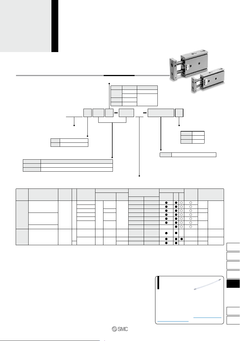
Dual Rod Cylinder
With Air Cushion
CXS Series
ø20, ø25, ø32
How to Order
Thread type
Bearing type
Slide bearing
Ball bushing bearing
Bore size/Stroke (mm)
20, 25, 30, 35, 40, 45, 50, 60, 70, 75, 80, 90, 100
25, 30, 35, 40, 45, 50, 60, 70, 75, 80, 90, 100
Air cushion
Auto switch
100 V or less
Load voltage
Wiring
(Output)
Pre-wired
connector
Applicable load
Bore size
ø20
ø25, ø32
Type
M thread
Rc
NPT
G
Symbol
Nil
TN
TF
Bore size
20
25, 32
Stroke
Nil
S
n
2 pcs.
1 pc.
“n” pcs.
Nil
Without auto switch (Built-in magnet)
For the applicable auto switch model,
refer to the table below.
∗
Special functionType
Electrical
entry
Indicator light
YesYes
Grommet
Grommet
Reed
auto switch
Solid state auto switch
Water resistant
(2-color indicator)
Diagnostic indication
(2-color indicator)
—
—
None
3-wire (NPN)
3-wire (PNP)
2-wire
3-wire (NPN)
3-wire (PNP)
2-wire
2-wire
3-wire
(NPN equivalent)
— —
—
—
—
—
—
—
—
—
—
—
—
IC
circuit
IC
circuit
IC
circuit
IC circuit
—
—
—
—
Relay,
PLC
Relay,
PLC
0.5
(Nil)
3
(L)
5
(Z)
Auto switch model
Perpendicular
In-line
• Since there are other applicable auto switches than listed, refer to page 758 for details.
• For details about auto switches with pre-wired connector, refer to pages 1192 and 1193.
• Auto switches are shipped together (not assembled).
∗ Solid state auto switches marked with “” are produced upon receipt of order.
∗∗ Water resistant type auto switches can be mounted on the above models, but in such case SMC cannot guarantee water resistance.
Consult with SMC regarding water resistant types with the above model numbers.
∗ Lead wire length symbols: 0.5 m ·········· Nil (Example) Y59A
3 m ·········· L (Example) Y59AL
5 m ·········· Z (Example) Y59AZ
761
CX2
CXW
CXT
CXSJ
CXS
D-
-X
CXS