6-2-2-p0723-0782-cxsj_en.pdf - 第55页
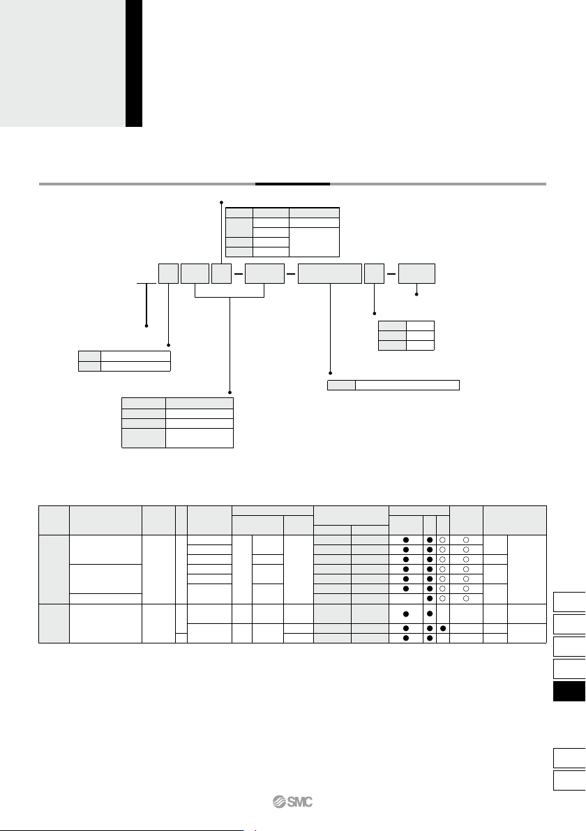
Applicable Auto Switches /Refer to pages 1119 to 1245 for further information on auto switches. How to Order Made to Order For details, refer to page 776. L Nil S n 2 pcs. 1 pc. “n” pcs. 100 20 Bearing type Slide bearing…
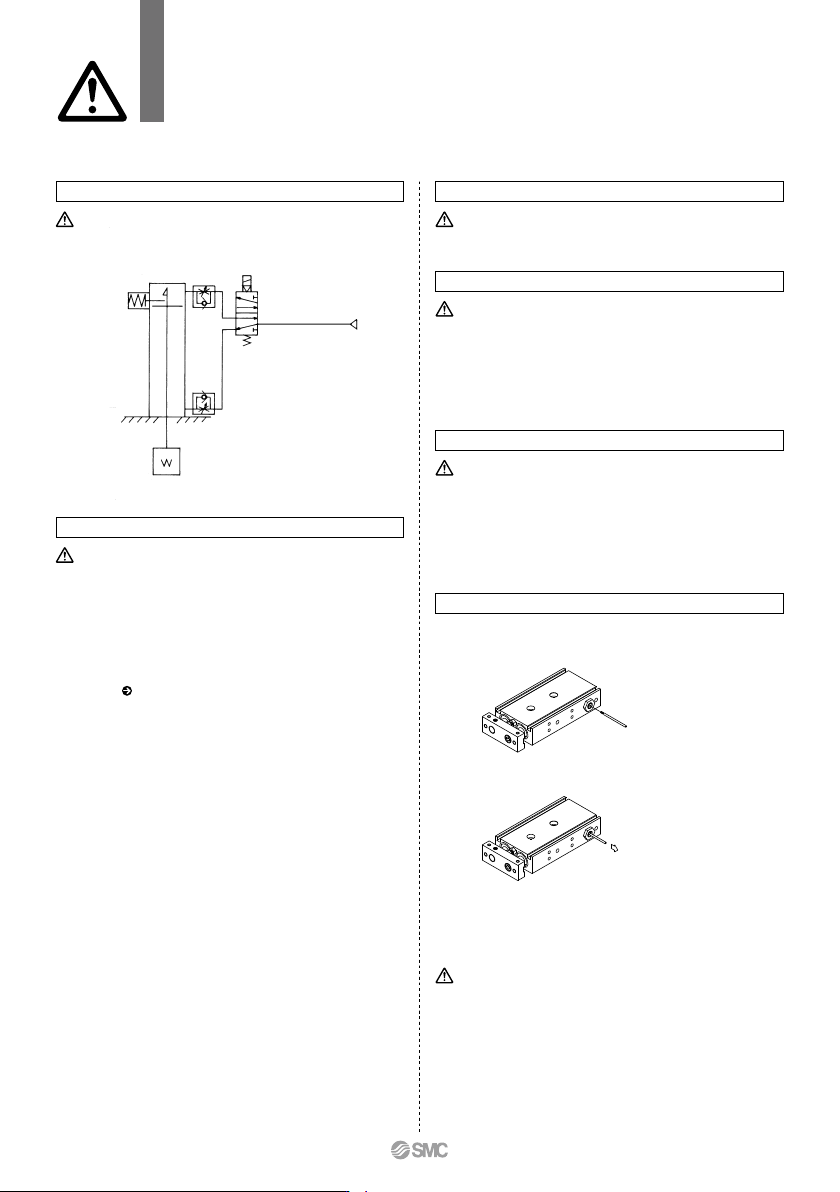
Recommended Pneumatic Circuit Operating Pressure
This is necessary for the proper operation and release of the lock.
Caution
Handling Precautions
Caution
1. Apply a pressure more than 0.3 MPa to the port on the head side.
The pressure is necessary to release the lock.
Caution
Exhaust Speed
1. Locking will occur automatically if the pressure applied to the port
on the head side falls to 0.05 MPa or less. In cases where the
piping on the head side is long and thin, or the speed controller is
separated at some distance from the cylinder port, the exhaust
speed will be reduced. Note that some time may be required for the
lock to engage. In addition, clogging of a silencer mounted on the
solenoid valve exhaust port can produce the same effect.
Caution
Releasing the lock
1. Before releasing the lock, be sure to supply air to the rod side, so
that there is no load applied to the lock mechanism when it is
released. (Refer to the Recommended Pneumatic Circuit.) If the
lock is released when the rod side is in an exhaust state, and with
a load applied to the lock unit, the lock unit may be subjected to an
excessive force and be damaged. Furthermore, sudden movement
of the slide table is extremely dangerous.
Warning
1. Do not use 3 position solenoid valves.
Avoid using in combination with 3 position solenoid valves
(especially closed center metal seal types). If pressure is trapped
in the port on the head side, the cylinder cannot be locked. Even
after being locked, the lock may be released after some time, due
to air leakage from the solenoid valve entering the cylinder.
2. Back pressure is required to release the end lock.
Be sure that air is supplied to the rod side before starting
operation, as shown in the drawing on the left. The lock may not be
released. ( Refer to the section on releasing the lock.)
3. Release the lock when mounting and adjusting the cylinder.
An attempt to mount or adjust a cylinder while it is locked can
damage the lock.
4. Operate with a load ratio of 50% or less.
If the load ratio exceeds 50%, this may cause problems such as
failure of the lock to release, or damage to the lock unit.
5. Do not operate multiple cylinders in synchronization.
Avoid applications in which two or more end lock cylinders are
synchronized to move one workpiece, as one of the cylinder locks
may not be able to release when required.
6. Install speed controllers as they will be meter-out control.
When they are used under meter-in control, the lock may not be
released.
7. Never adjust the retracting stroke using a bumper bolt or
external stopper. The lock will not function.
1. Insert the manual lever and screw it into the lock holder assembly.
If the lever is screwed in sidelong, it may damage the lock spring.
2. To unlock, pull the manual lever in the direction of the arrow.
Release the manual lever to return the cylinder to a ready-to-lock
state.
3.
The manual lever (ø1.6 x 35 L, tip part: M1.6 x 0.35 x 3 L) is included
with the cylinder. If additional manual levers are required, use the
following part number to place an order: CXS06-48BK2777 (for all
series).
Manual Release
Manual release (Non-locking type)
CXS Series
With End Lock for Retraction Side
Specific Product Precautions
Be sure to read this before handling the products.
Refer to back page 50 for Safety Instructions and pages 3 to 12 for Actuator and
Auto Switch Precautions.
Do not use the cylinder while the manual lever is screwed in. It may
damage the lock mechanism.
Caution
774
Applicable Auto Switches/Refer to pages 1119 to 1245 for further information on auto switches.
How to Order
Made to Order
For details, refer to page 776.
L
Nil
S
n
2 pcs.
1 pc.
“n” pcs.
10020
Bearing type
Slide bearing
Ball bushing bearing
CXS W
Double rod type
M
L
Nimber of auto switches
Bore size/Stroke (mm)
Bore size
10, 20, 30, 40, 50
10, 20, 30, 40, 50
10, 20, 30, 40, 50,
75, 100
6
10, 15
20, 25, 32
Auto switch
Nil
Without auto switch (Built-in magnet)
Standard stroke
Y7BW
∗ For the applicable auto switch model,
refer to the table below.
Thread type
Bore size
ø6 to ø20
ø25, ø32
Type
M thread
Rc 1/8
NPT 1/8
G 1/8
Symbol
Nil
TN
TF
AC
DC
Lead wire length (m)
∗
5 V
5 V, 12 V
12 V
5 V, 12 V
12 V
24 V
Z76
Z73
Y59A
Y7P
Y59B
Y7NW
Y7PW
Y7BW
Y7BA
∗∗
Y69A
Y7PV
Y69B
Y7NWV
Y7PWV
Y7BWV
100 V
24 V 12 V
Z73
Z80
100 V or less
Load voltage
Wiring
(Output)
Pre-wired
connector
Applicable load
Special functionType
Electrical
entry
Indicator light
YesYes
Grommet
Grommet
Reed
auto switch
Solid state auto switch
Water resistant
(2-color indicator)
Diagnostic indication
(2-color indicator)
—
—
None
3-wire (NPN)
3-wire (PNP)
2-wire
3-wire (NPN)
3-wire (PNP)
2-wire
2-wire
3-wire
(NPN equivalent)
— —
—
—
—
—
—
—
—
—
—
—
—
IC
circuit
IC
circuit
IC
circuit
IC circuit
—
—
—
—
Relay,
PLC
Relay,
PLC
0.5
(Nil)
3
(L)
5
(Z)
Auto switch model
Perpendicular
In-line
• Since there are other applicable auto switches than listed, refer to page 758 for details.
• For details about auto switches with pre-wired connector, refer to pages 1192 and 1193.
• Auto switches are shipped together (not assembled).
∗ Solid state auto switches marked with “” are produced upon receipt of order.
∗∗ Water resistant type auto switches can be mounted on the above models, but in such case SMC cannot guarantee water resistance.
Consult with SMC regarding water resistant types with the above model numbers.
∗ Lead wire length symbols: 0.5 m ·········· Nil (Example) Y59A
3 m ·········· L (Example) Y59AL
5 m ·········· Z (Example) Y59AZ
Dual Rod Cylinder
Double Rod Type
ø6, ø10, ø15, ø20, ø25, ø32
CXSW Series
775
CX2
CXW
CXT
CXSJ
CXS
D-
-X
CXS
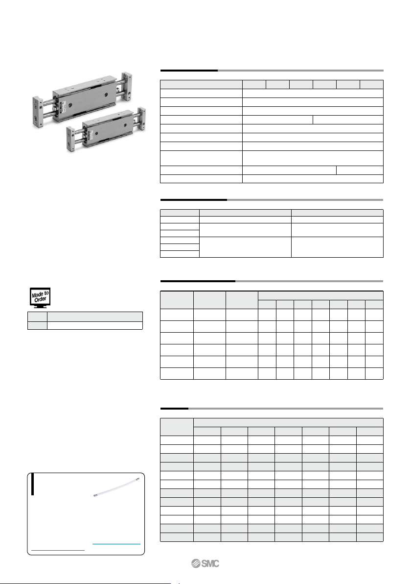
When operating an actuator with a small diameter
and a short stroke at a high frequency, the dew
condensation (water droplet) may occur inside the
piping depending on the conditions.
Simply connecting the moisture control tube to the
actuator will prevent dew condensation from oc-
curring. For details, refer to the IDK series in the
Best Pneumatics No. 6.
Moisture
Control Tube
IDK Series
Specifications
Bore size (mm)
Fluid
Proof pressure
Maximum operating pressure
Minimum operating pressure
Ambient and fluid temperature
Piston speed
Cushion
Stroke adjustable range
Port size
Bearing type
6 10 15
Air (Non-lube)
1.05 MPa
0.7 MPa
–10 to 60°C (No freezing)
50 to 500 mm/s
Bumper is standard on both ends
0 to –10 mm compared to the standard stroke
(Extended end: 5 mm, Retracted end: 5 mm)
Slide bearing, Ball bushing bearing (Same dimensions for both)
0.15 MPa 0.1 MPa
20 25 32
Note) Theoretical output (N) = Pressure (MPa) x Piston area (mm
2
)
∗ For long strokes, it will be made-to-order. (–XB11)
(N)
(kg)
Model
CXSW 6
CXSW10
CXSW15
CXSW20
CXSW25
CXSW32
Rod size
(mm)
4
6
8
10
12
16
4.6
10
25.2
47.1
75.6
121
6.2
20
50.4
94.2
151
241
9.3
30
75.6
141
227
362
12.4
40
101
188
302
482
15.5
50
126
236
378
603
18.6
60
151
283
454
724
21.7
70
176
330
529
844
0.1 0.2 0.3 0.4
Operating pressure (MPa)
0.5 0.6 0.7
Model
10
0.11
0.12
0.24
0.25
0.43
0.47
0.71
0.75
1.06
1.07
2.04
2.06
20
0.13
0.13
0.26
0.27
0.45
0.50
0.74
0.79
1.11
1.12
2.12
2.15
30
0.14
0.15
0.28
0.29
0.48
0.52
0.78
0.82
1.17
1.18
2.21
2.23
40
0.16
0.16
0.30
0.31
0.51
0.55
0.82
0.86
1.22
1.23
2.29
2.32
50
0.17
0.18
0.32
0.33
0.54
0.58
0.85
0.90
1.28
1.29
2.38
2.41
75
—
—
0.37
0.38
0.61
0.65
0.95
0.99
1.41
1.42
2.59
2.62
100
—
—
0.42
0.43
0.68
0.42
1.04
1.08
1.55
1.56
2.81
2.83
Standard stroke (mm)
CXSWM
CXSWL
CXSWM
CXSWL
CXSWM
CXSWL
CXSWM
CXSWL
CXSWM
CXSWL
CXSWM
CXSWL
6
6
10
10
15
15
20
20
25
25
32
32
Piston area
(mm
2
)
31
100
252
471
756
1206
M5 x 0.8 Rc 1/8
Standard Stroke
CXSW 6
CXSW10
CXSW15
CXSW20
CXSW25
CXWS32
Model
(mm)
Theoretical Output
Weight
Standard stroke
10, 20, 30, 40, 50
10, 20, 30, 40, 50, 75, 100
10, 20, 30, 40, 50
Long stroke
—
125, 150, 175, 200
75, 100, 125, 150
–XB11 Long stroke
Symbol Specifications
Made to Order Specifications
Click here for details
CXSW Series
776
A