6-2-2-p0723-0782-cxsj_en.pdf - 第42页
Weight 628 471 982 756 1608 1206 0.2 126 94.2 196 151 322 241 0.3 188 141 295 227 482 362 0.4 251 188 393 302 643 482 0.5 314 236 491 378 804 603 0.6 377 283 589 454 965 724 0.7 440 330 687 529 1126 844 0.1 62.8 47.1 98.…
When operating an actuator with a small diameter
and a short stroke at a high frequency, the dew
condensation (water droplet) may occur inside the
piping depending on the conditions.
Simply connecting the moisture control tube to the
actuator will prevent dew condensation from oc-
curring. For details, refer to the IDK series in the
Best Pneumatics No. 6.
Moisture
Control Tube
IDK Series
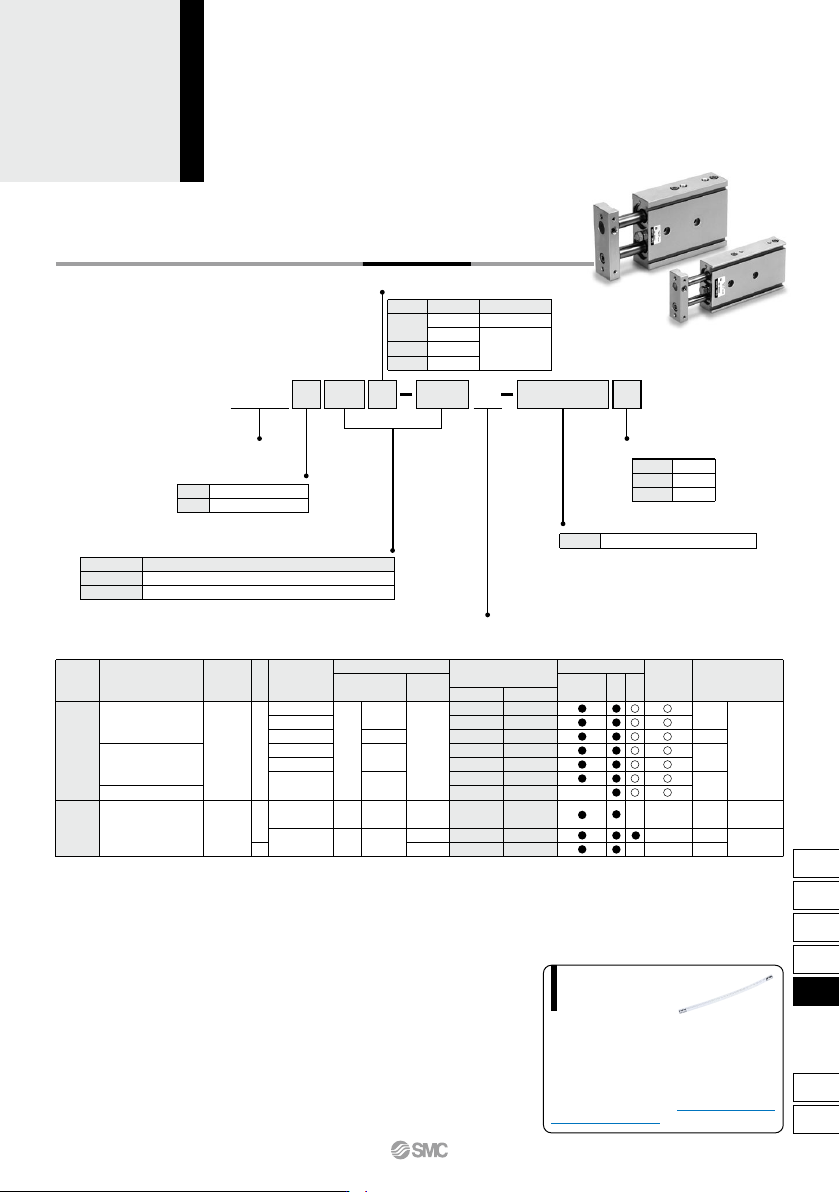
CXS M 100 A20
M
L
Dual Rod Cylinder
Number of auto switches
(No. of auto switch)
Y7BW
Applicable Auto Switches/Refer to pages 1119 to 1245 for further information on auto switches.
AC
DC
Lead wire length (m)
∗
5 V
5 V, 12 V
12 V
5 V, 12 V
12 V
24 V
Z76
Z73
Y59A
Y7P
Y59B
Y7NW
Y7PW
Y7BW
Y7BA
∗∗
Y69A
Y7PV
Y69B
Y7NWV
Y7PWV
Y7BWV
100 V
24 V 12 V
Z73
Z80
Dual Rod Cylinder
With Air Cushion
CXS Series
ø20, ø25, ø32
How to Order
Thread type
Bearing type
Slide bearing
Ball bushing bearing
Bore size/Stroke (mm)
20, 25, 30, 35, 40, 45, 50, 60, 70, 75, 80, 90, 100
25, 30, 35, 40, 45, 50, 60, 70, 75, 80, 90, 100
Air cushion
Auto switch
100 V or less
Load voltage
Wiring
(Output)
Pre-wired
connector
Applicable load
Bore size
ø20
ø25, ø32
Type
M thread
Rc
NPT
G
Symbol
Nil
TN
TF
Bore size
20
25, 32
Stroke
Nil
S
n
2 pcs.
1 pc.
“n” pcs.
Nil
Without auto switch (Built-in magnet)
For the applicable auto switch model,
refer to the table below.
∗
Special functionType
Electrical
entry
Indicator light
YesYes
Grommet
Grommet
Reed
auto switch
Solid state auto switch
Water resistant
(2-color indicator)
Diagnostic indication
(2-color indicator)
—
—
None
3-wire (NPN)
3-wire (PNP)
2-wire
3-wire (NPN)
3-wire (PNP)
2-wire
2-wire
3-wire
(NPN equivalent)
— —
—
—
—
—
—
—
—
—
—
—
—
IC
circuit
IC
circuit
IC
circuit
IC circuit
—
—
—
—
Relay,
PLC
Relay,
PLC
0.5
(Nil)
3
(L)
5
(Z)
Auto switch model
Perpendicular
In-line
• Since there are other applicable auto switches than listed, refer to page 758 for details.
• For details about auto switches with pre-wired connector, refer to pages 1192 and 1193.
• Auto switches are shipped together (not assembled).
∗ Solid state auto switches marked with “” are produced upon receipt of order.
∗∗ Water resistant type auto switches can be mounted on the above models, but in such case SMC cannot guarantee water resistance.
Consult with SMC regarding water resistant types with the above model numbers.
∗ Lead wire length symbols: 0.5 m ·········· Nil (Example) Y59A
3 m ·········· L (Example) Y59AL
5 m ·········· Z (Example) Y59AZ
761
CX2
CXW
CXT
CXSJ
CXS
D-
-X
CXS
Weight
628
471
982
756
1608
1206
0.2
126
94.2
196
151
322
241
0.3
188
141
295
227
482
362
0.4
251
188
393
302
643
482
0.5
314
236
491
378
804
603
0.6
377
283
589
454
965
724
0.7
440
330
687
529
1126
844
0.1
62.8
47.1
98.2
75.6
161
121
OUT
IN
OUT
IN
OUT
IN
10
12
16
20
0.50
0.52
—
—
—
—
25
0.52
0.54
0.78
0.79
1.48
1.51
30
0.54
0.56
0.80
0.81
1.53
1.55
35
0.56
0.58
0.82
0.83
1.575
1.60
40
0.58
0.60
0.84
0.85
1.62
1.64
45
0.60
0.62
0.86
0.87
1.67
1.69
50
0.62
0.64
0.88
0.89
1.72
1.74
60
0.66
0.68
0.92
0.93
1.82
1.84
70
0.70
0.72
0.96
0.97
1.92
1.94
75
0.715
0.735
0.98
0.99
1.96
1.98
80
0.735
0.755
1.00
1.01
2.06
2.08
90
0.755
0.775
1.04
1.05
2.14
2.16
100
0.815
0.835
1.08
1.09
2.20
2.22
Specifications
32
5.9
5.7
5.6
0.40
0.75
1.0
20
25
32
Cushion Needle Adjustment
(N)
2520
Precautions
Be sure to read this before handling
the products.
Refer to back page 50 for Safety
Instructions and pages 3 to 12 for
Actuator and Auto Switch Precautions.
Selection
Caution
Caution
1.
Operate the cylinder until the stroke end.
If the stroke is restricted by the external
stopper and clamp workpiece, effective
cushioning and noise reduction will not be
achieved.
2. Adjust the cushion needles to absorb
the kinetic energy during the cushion
stroke so that excessive kinitic energy
does not remain when the piston reach-
es the stroke end.
If the piston reaches the stroke end with ex-
cessive kinetic energy remaining (more
than the values given in table (1) below)
due to an improper adjustment, excessive
impact will occur, causing damage to ma-
chinery.
Table (1) Allowable Value at Piston Impact
Bore size (mm)
Piston speed (mm/s)
Kinetic energy (J)
25
50 to 600
0.27
20
50 to 700
0.17
32
50 to 600
0.32
1.Keep the adjusting range for the cush-
ion needle between the fully closed
position and the rotations shown below.
Bore size (mm)
Rotations
2520
32
3 rotations or less
2.5 rotations or less
Use a 3 mm flat head watchmakers screw-
driver to adjust the cushion needles to the
fully closed position, as this will cause dam-
age to the seals. The adjusting range for the
cushion needles must be between the fully
closed position and the open position rang-
es indicated in the table above. A retaining
mechanism prevents the cushion needles
from slipping out; however, they may spring
out during operation if they are rotated be-
yond the ranges shown above.
Precautions for selection standard, mount-
ing, piping, and operating environment are
same as for the standard series.
Fluid
Proof pressure
Maximum operating pressure
Minimum operating pressure
Ambient and fluid temperature
Piston speed
Port size
Bearing type
Cushion
Bore size (mm)
Air (Non-lube)
1.05 MPa
0.7 MPa
0.1 MPa
–10 to 60°C (No freezing)
50 to 1000 mm/s
M5 x 0.8
Rc 1/8 (NPT 1/8, G 1/8)
Slide bearing, Ball bushing bearing (Same dimensions for both)
Air cushion (Both ends)
Cushion mechanism
Absorbable kinetic energy (J)
Effective cushion length
(mm)
Bore size
(mm)
Standard Stroke
CXS20
CXS25
CXS32
Model
Standard stroke
20, 25, 30, 35, 40, 45, 50, 60, 70, 75, 80, 90, 100
(mm)
25, 30, 35, 40, 45, 50, 60, 70, 75, 80, 90, 100
Theoretical Output
CXS20
CXS25
CXS32
Model
Operating
direction
Operating pressure (MPa)
Rod size
(mm)
Piston area
(mm
2
)
Note) Theoretical output (N) = Pressure (MPa) x Piston area (mm
2
)
Model
CXSM20-A
CXSL20-A
CXSM25-A
CXSL25-A
CXSM32-A
CXSL32-A
Standard stroke (mm)
(kg)
∗ Maximum load mass is the same as the standard type.
CXS Series
762
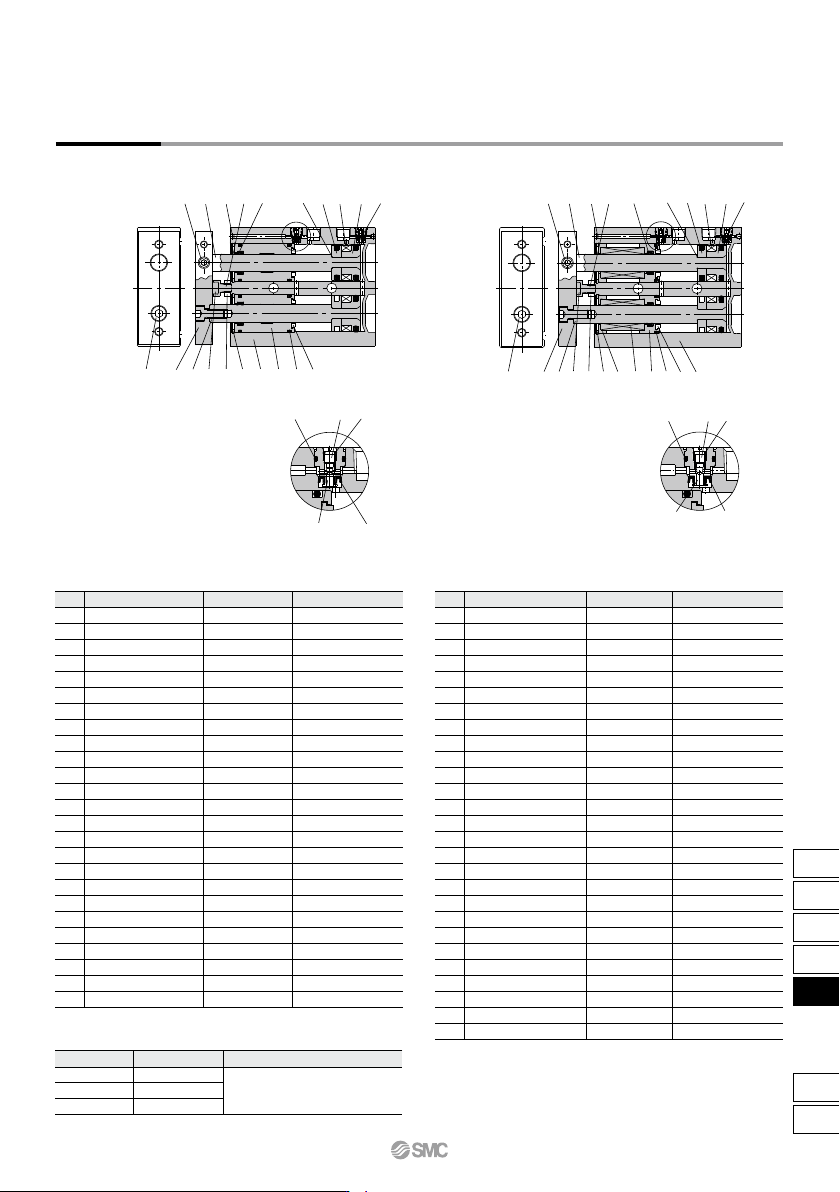
CXSM/With air cushion
Construction
CXSL/With air cushion
Component Parts: CXSM
No. Description
Housing
Piston rod A
Piston rod B
Rod cover
Plate
Piston A
Piston B
Bumper B
Magnet
Bumper bolt
Hexagon nut
Bumper
Hexagon socket head cap screw
Hexagon socket head set screw
Retaining ring
Steel ball
Piston seal
Rod seal
O-ring
O-ring
Cushion needle
Check seal retainer
Check seal
Needle gasket
Check gasket
Material
Aluminum alloy
Carbon steel
Carbon steel
Aluminum bearing alloy
Aluminum alloy
Aluminum alloy
Aluminum alloy
Urethane
—
Carbon steel
Carbon steel
Urethane
Chromium steel
Chromium steel
Special steel
Special steel
NBR
NBR
NBR
NBR
Stainless steel
Copper alloy
NBR
NBR
NBR
Note
Hard anodized
Hard chrome plated
Hard chrome plated
Anodized
Chromated
Chromated
Nickel plated
Zinc chromated
Zinc chromated
Zinc chromated
Phosphate coated
Nickel plated
1
2
3
4
5
6
7
8
9
10
11
12
13
14
15
16
17
18
19
20
21
22
23
24
25
Replacement Parts/Seal Kit
Kit no.
CXS20A-PS
CXS25A-PS
CXS32A-PS
Bore size (mm)
20
25
32
Contents
Component Parts: CXSL
No. Description
Housing
Piston rod A
Piston rod B
Bearing spacer
Ball bushing
Bumper holder
Plate
Piston A
Piston B
Bumper B
Magnet
Bumper bolt
Hexagon nut
Bumper
Hexagon socket head cap screw
Hexagon socket head set screw
Retaining ring
Steel ball
Piston seal
Rod seal
O-ring
O-ring
Cushion needle
Check seal retainer
Check seal
Needle gasket
Check gasket
Material
Aluminum alloy
Special steel
Special steel
Aluminum alloy
—
Aluminum alloy
Aluminum alloy
Aluminum alloy
Aluminum alloy
Urethane
—
Carbon steel
Carbon steel
Urethane
Chromium steel
Chromium steel
Special steel
Special steel
NBR
NBR
NBR
NBR
Stainless steel
Copper alloy
NBR
NBR
NBR
Note
Hard anodized
Hard chrome plated
Hard chrome plated
Anodized
Chromated
Chromated
Nickel plated
Zinc chromated
Zinc chromated
Zinc chromated
Phosphate coated
Nickel plated
1
2
3
4
5
6
7
8
9
10
11
12
13
14
15
16
17
18
19
20
21
22
23
24
25
26
27
∗ Seal kit includes !7, !8 and !9. Order the seal kit, based on each bore size.
∗ Since the seal kit does not include a grease pack, order it separately.
Grease pack part no.: GR-S-010 (10 g)
CXSM: Set of nos. !7, !8 and !9
CXSL: Set of nos. !9, @0 and @1
Close-up of AClose-up of A
CXS Series
Dual Rod Cylinder
With Air Cushion
!3 !2e !1
!0
q r
u
@4
@0
@3
@1
@2
!7
!4
w
!8
o
!6
y
i
A
@5
!5 !9t
!3
!2
ye
!1
o
!0
q
!5
u t
@7
@4
@5
@3
@2
@6
!9
!4
w
@0
!8
r
!6 i
!7
@1
A
763
CX2
CXW
CXT
CXSJ
CXS
D-
-X
CXS