6-2-2-p0723-0782-cxsj_en.pdf - 第25页
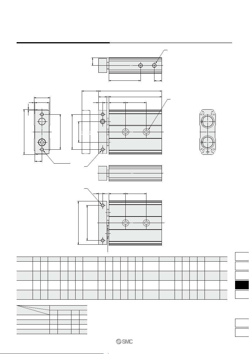
A 54 62 73 94 B 19 24 29 37 C 52 60 71 92 D 17 22 27 35 E 8.5 11 13.5 17.5 G 42 50 60 75 H 25 29 35 45 I 5 6 6 8 J 10 12 12 16 K 2.5 4.5 4.5 4 L 20 25 30 30 NN ø8 ø10 ø12 ø16 Q 9.5 12 14.5 18.5 R 38 45 46 56 T 9 9 9 10 M…
CXSJ6P
CXSJ10P
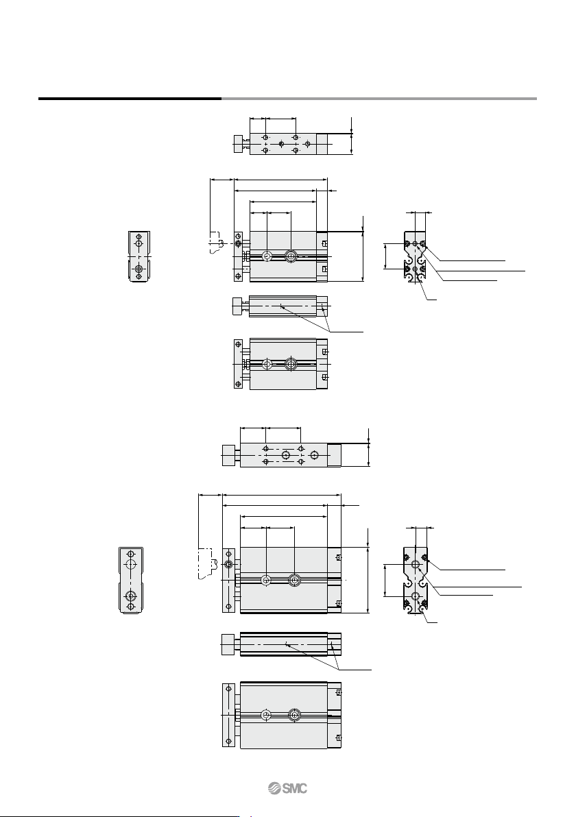
Dimensions: ø6, ø10 Axial Piping
5 + Stroke
12
ST
6.7
7
0.3
0.3
16
31.4
(49 + Stroke)
9 + Stroke
10
32 + Stroke
42 + Stroke
12.8
4 x M1.6 x 0.35 x 6 L
2 x M3 x 0.5 thread depth 3
(Piping port) OUT
Steel balls
IN
8.5
7.5
ST
8 + Stroke
16
56 + Stroke
44.5 + Stroke
0.3
14.4
0.341.4
20
(64.5 + Stroke)
Steel balls
4 x M1.6 x 0.35 x 8 L
2 x M5 x 0.8 thread depth 4
(Piping port) OUT
IN
12 + Stroke
16
CXSJ Series
744
A
54
62
73
94
B
19
24
29
37
C
52
60
71
92
D
17
22
27
35
E
8.5
11
13.5
17.5
G
42
50
60
75
H
25
29
35
45
I
5
6
6
8
J
10
12
12
16
K
2.5
4.5
4.5
4
L
20
25
30
30
NN
ø8
ø10
ø12
ø16
Q
9.5
12
14.5
18.5
R
38
45
46
56
T
9
9
9
10
MF
2 x M5 x 0.8
2 x M5 x 0.8
2 x M6 x 1.0
2 x M6 x 1.0
ZZ
70
84
87
100.5
15
20
25
32
15
20
25
32
Bore size (mm)
2 x 2 x ø4.3 through
2 x 2 x ø8 counterbore
with depth 4.3
2 x 2 x ø5.5 through
2 x 2 x ø9.5 counterbore
with depth 5.3
2 x 2 x ø6.5 through
2 x 2 x ø11 counterbore
with depth 6.3
2 x 2 x ø6.5 through
2 x 2 x ø11 counterbore
with depth 6.3
N
2 x M4 x 0.7
with thread
depth 6
2 x M4 x 0.7
with thread
depth 6
2 x M5 x 0.8
with thread
depth 7.5
2 x M5 x 0.8
with thread
depth 7.5
U
2 x M5 x 0.8
with thread
depth 4
2 x M5 x 0.8
with thread
depth 4
2 x M5 x 0.8
with thread
depth 4
2 x Rc1/8
with thread
depth 5
10, 20
25
30
30
40
30, 40, 50
35
40
40
50
75
45
60
60
70
100
55
60
60
70
Z
Symbol
Stroke
Bore size (mm)
SS
57.5
67.5
70.5
80.5
Dimensions: ø15 to 32 Standard Piping
Stroke
R
T
H
(G)
(G)
C
NN
(I )
A
G
± 0.2
M
F
(Through)
N
I
J
K
SS + Stroke
L
Z
ZZ + Stroke
1
1
D
B
E
Q
(L) (Z)
U
N
CXSJ Series
Dual Rod Cylinder
Compact Type
745
CX2
CXW
CXT
CXSJ
CXS
D-
-X
CXSJ
C
D
A
B
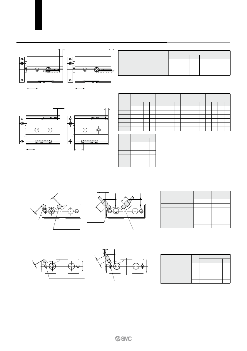
D-A9
(Reed switch)
D-M9W
D-M9
D-M9A
(Solid state switch)
D-M9V
D-M9WV
D-M9AV
(Solid state switch)
D
1
D
2
C
2
C1
C3
B
1
A1
A
B
C
D
D-A9 (Reed switch)
D-M9 (Solid state switch)
D-M9W
D-M9A
D-A9V (Reed switch)
D-M9V (Solid state switch)
D-M9WV
D-M9AV
A
1
C
1
C3
C2
Electrical entry direction:
Inward
Electrical entry direction:
Outward
D-A9V
(Reed switch)
CXSJ6, 10
CXSJ6,10
CXSJ15 to 32
CXSJ15 to 32
Auto switch mounting dimensions
Symbol
A1
A1
C1
C2
C3
15 20 25
1
2
5.5
4.5
1
1
2
5.5
4.5
—
1
2
5.5
4.5
—
1
2
5.5
4.5
—
32
D-M9, D-M9W
D-M9A
D-A9V
D-M9WV
D-M9AV
Auto switch model
(mm)
(mm)
D-A9, D-A9V
D-M9, D-M9V
D-M9A, D-M9AV
D-M9W, D-M9WV
Auto switch model
Bore size
Operating Range
Auto Switch Proper Mounting Position
6
5
2.5
10
6
3
15
6
3.5
20
7.5
4.5
25
8
4.5
32
9
5
A
15.5
25.5
31.5
39
40
49
B
—
—
6
9
11
11.5
C
13.5
23.5
29.5
37
38
47
D
5.5
3
4
7
9
9.5
A
15.5
25.5
31.5
39
40
49
B
—
—
6
9
11
11.5
C
11
21
27
34.5
35.5
44.5
D
8
5.5
1.5
4.5
6.5
7
A
19.5
29.5
35.5
43
44
53
B
0.5
3
10
13
15
15.5
C
9.5
19.5
25.5
33
34
43
D
9.5
7
0
3
5
5.5
6
10
15
20
25
32
Bore size
(mm)
D-M9
, D-M9
W
D-M9
AV
D-A93D-A90, D-A96
A
19.5
29.5
35.5
43
44
53
B
0.5
3
10
13
15
15.5
C
7.5
17.5
23.5
31
32
41
D
11.5
9
2
5
7
7.5
6
10
15
20
25
32
Bore size
(mm)
D-M9A
A
19.5
29.5
35.5
43
44
53
B
0.5
3
10
13
15
15.5
C
11.5
21.5
27.5
35
36
45
D
7.5
5
2
5
7
7.5
D-M9V, D-M9WV
Bore size
∗ The operating ranges are provided as guidelines including hystereses and are not
guaranteed values (assuming approximately ±30% variations).
They may vary significantly with ambient environments.
Symbol
A1
B1
B1
C1, D1
C2, C3, D2
C1, D1
C2, C3, D2
6
1
1
2
5.5
4
8
6
1
1
2
5.5
4
8
6
10
Bore size
D-A9
D-M9,
D-M9W
D-M9A
D-A9V
D-M9V, D-M9WV
D-M9AV
Auto switch model
(mm)
Auto Switch Proper Mounting Position for Stroke End Detection
Note 1) ø6: D-A90, A96, A93, F9BA
ø10: D-A90, A96, A93
Only outward electrical entry (D dimen-
sion) is available.
Note 2) Minus value in D column (ø15, ø20, ø25,
ø32) means that the auto switches are to
be mounted beyond the cylinder body
edges.
Note 3) When setting an auto switch, confirm the
operation and adjust its mounting position.
CXSJ Series
Auto Switch Mounting
746