Specification E by SIPLACE 规格说明书.pdf - 第16页
16 PCB Warpage PCB warpage across the dire ction of travel max. 1 % of the PCB diagonal, but not exceeding 2 mm PCB warpage on the conveyor Fixed clamped edge Movable clamping device PCB Fixed clamped edge Conveyor belt …
15
Board Conveyor
Technical Data
Single conveyor
Standard dimensions (length x width)
With buffering
Without buffering
a
a) On request
50 mm x 50 mm to 460 mm x 460 mm
50 mm x 50 mm to 490 mm x 460 mm
With “Long Board”option 1030 (length x width)
Single step mode
Two step mode
a
50 mm x 50 mm to 610 mm x 460 mm
50 mm x 50 mm to 1030 mm x 460 mm
With “Long Board”option 1200 (length x width) 70 mm x 50 mm to 1200 mm x 460 mm
Stationary conveyor side Right, Left
Automatic electrical width adjustment Standard
PCB thickness
Standard 0.3 mm to 4.5 mm
PCB warpage See page 16
PCB weight
b
Standard
b) The board weight value refers to the weight of the board plus the weight of the components.
max. 2.0 kg
Clearance on PCB underside
c
c) The free positioning of support pins is limited by the stop bar.
25 mm
PCB conveyor height
Standard:
Option:
900 mm to 930 mm
950 mm
Type of interface:
Standard: SMEMA or IPC-HERMES-9852
Component-free PCB handling edge 3.0 mm
PCB changeover time
Single conveyor < 1.5 seconds
IPC-HERMES-9852
A protocol for advanced development of Industry 4.0 in electronics production
The Hermes Standard, also published as IPC-HERMES-9852, is a non-proprietary open protocol,
based on TCP / IP and XML. This boosts the exchange of PCB-relevant data between the various
machines in the electronics production lines. The Hermes Standard was initiated, developed and
established and is still managed by a group of leading equipment manufacturers, who share their
know-how to achieve a significant step towards advanced process integration. It has been
recognized by IPC as the next generation solution for IPC-SMEMA-9851, normally known as
"SMEMA standard". The founding and defining body The Hermes Standard Initiative is available
to all equipment providers wanting to actively participate in using the benefits of Industry 4.0 for
their customers.
16
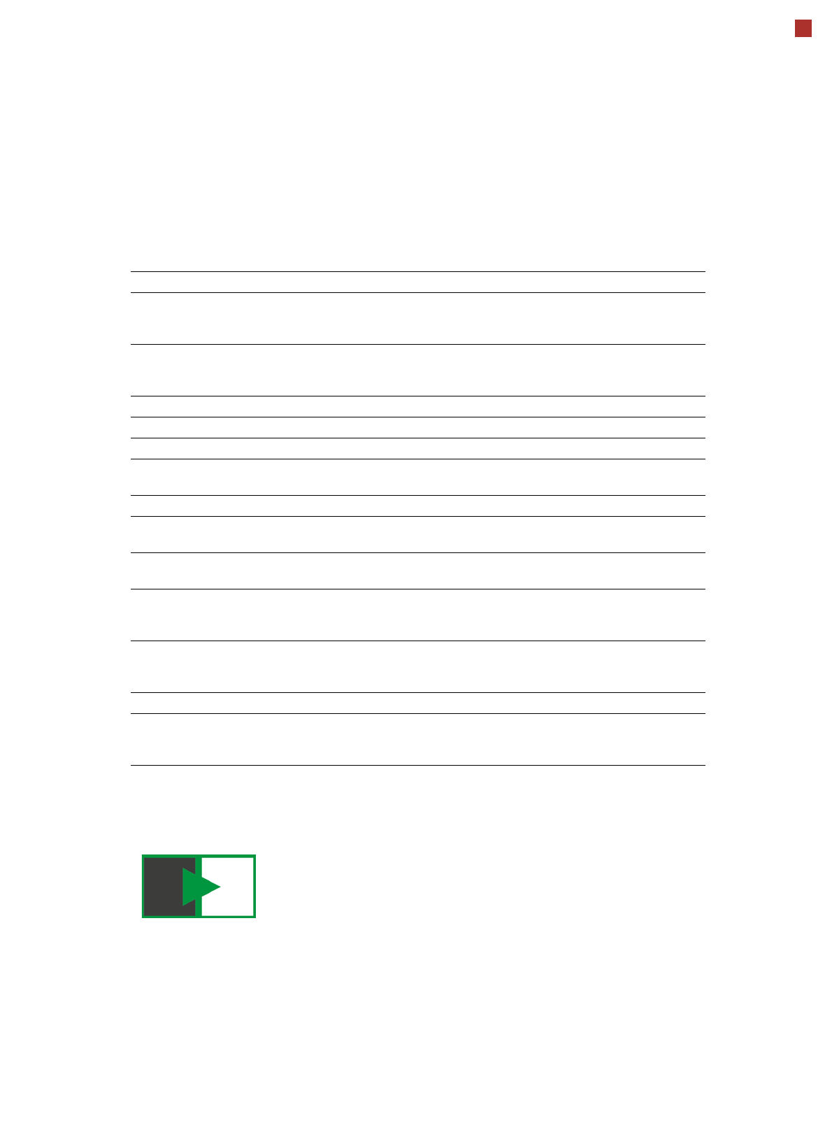
PCB Warpage
PCB warpage across the direction of travel
max. 1 % of the PCB diagonal, but not
exceeding 2 mm
PCB warpage on the conveyor
Fixed clamped edge
Movable clamping device
PCB
Fixed clamped edge
Conveyor belt
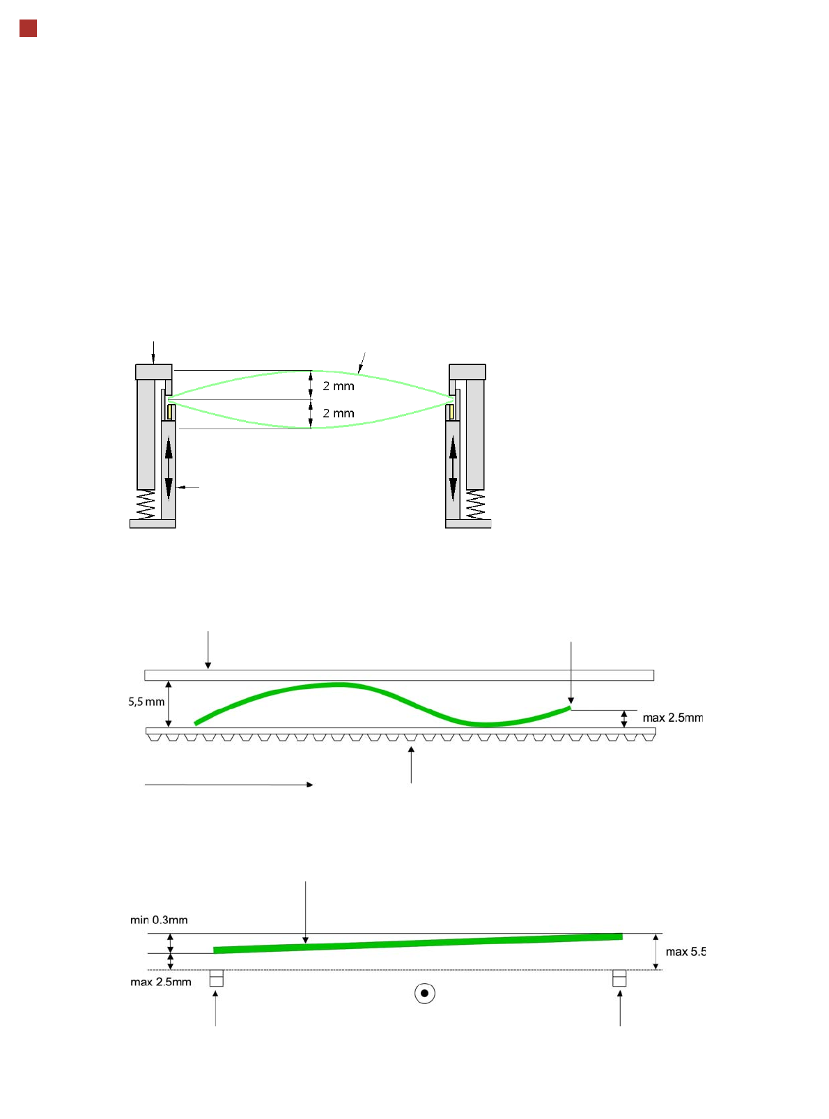
PCB transport direction
Front board edge
Front board edge
PCB warpage in direction of travel + PCB thickness < 5.5 mm
Bending up of front board edge max. 2.5 mm
Left conveyor belt
Right conveyor belt
PCB transport direction
17
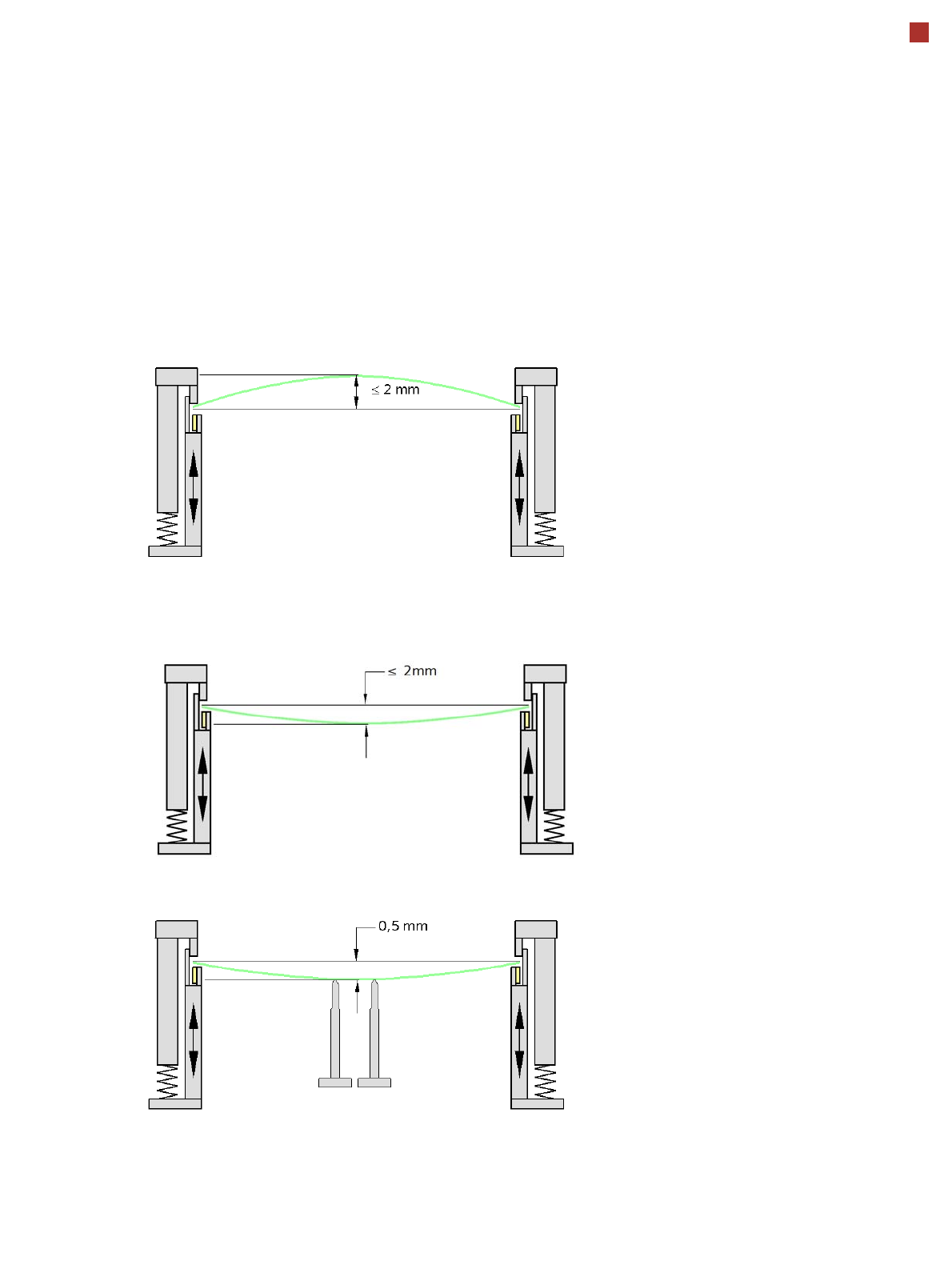
PCB Warpage
PCB warpage during placement
To avoid impairing the placement quality and
speed, we recommend using a PCB support e.g.
Smart Pin Support so that the PCB warpage
downwards does not exceed 0.5 mm.
PCB warpage up, max. 2 mm
PCB support
PCB warpage down, max. 2 mm
Changes in the surface position are automatically applied by the functions for learning the height.