Specification E by SIPLACE 规格说明书.pdf - 第34页
34 ASM Software Products Overview Workflows ASM Software Product St andard Opt ion Planning ASM Production Planner Fully automatic product grouping and optimization by taking del iv- ery deadlines into account X SIPLACE …
33
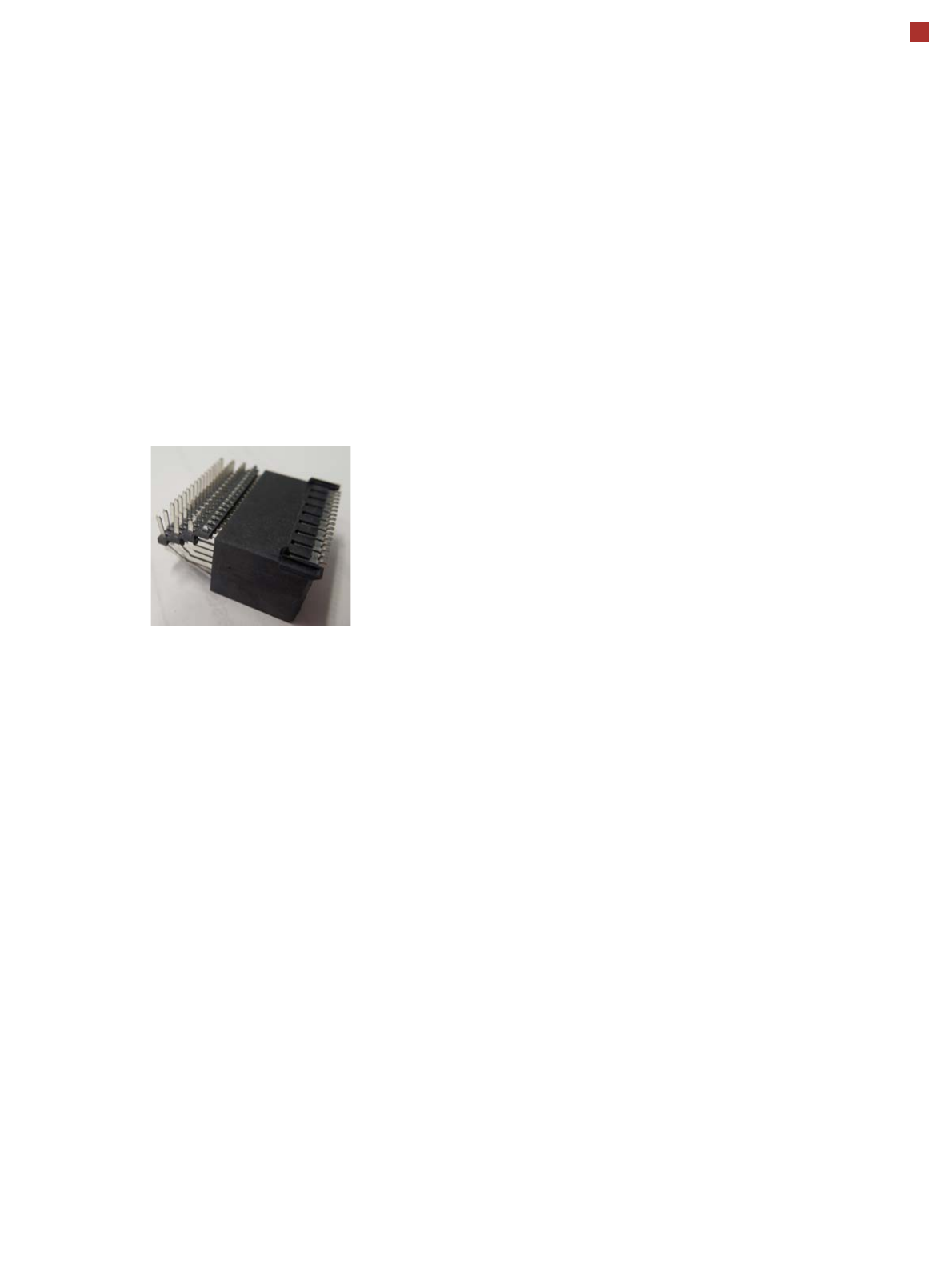
OSC package
The licensed OSC package
contains functions for simpli-
fied placement of odd
shaped components (OSC),
such as connectors or sock-
ets.
The license is activated via
SIPLACE PRO.
For detailed information,
refer to the OSC package
user guide, item number
[00198374-xx].
The following functions are
contained in the OSC pack-
age:
OSC measurement options
• Customized odd shaped
component
This enables the user to
describe any abstract pat-
tern on a component e.g.
connection leads of a tri-
angular shape. This pat-
tern can then be easily
created and edited at the
station, using the wizard
function.
• Stereo measurement
Stereo measurement
means that two images
are taken of each compo-
nent, from different direc-
tions, using a stationary
camera. These images
are overlapped to show
connectors, pins etc. in 3D
to support easy and pre-
cise evaluation of struc-
tures which, due to color,
shading or background
structures, are difficult to
recognize in conventional
2D measurement.
• Special position evalua-
tion
This function supports
separate definition of posi-
tion-determining features
(x,y, angle) independent
of the features for good-
bad recognition.
Placement of snap-in com-
ponents
This function monitors
whether snap-in components
engage in the board prop-
erly, during automatic place-
ment.
Automatic calculation of
optimum acceleration
This function enables the
user to automatically calcu-
late the optimum accelera-
tion of individual axes for a
component at the station.
The acceleration values
found can then be checked in
an additional test run and
sent back to the program-
ming system if successful.
Pin in paste height check
This option extends the
"snap-in" function for CPP
and Twin heads.
Placement of very high
components
In special application cases
the software can place a very
high component with auto-
matic collision prevention.
Additional force levels for
TH and CPP head
•30 N for TH

34
ASM Software Products
Overview
Workflows ASM Software Product Standard Option
Planning
ASM Production Planner
Fully automatic product grouping and optimization by taking deliv-
ery deadlines into account
X
SIPLACE SiCluster Professional / SiCluster Multiline
Fully automatic product grouping
X
Virtual production
SIPLACE Pro
One application for all programming tasks
X
SIPLACE LED Pairing
Simple placement of LEDs with multiple classes
X
Production
SIPLACE Station Software
Diverse operating system
X
ASM OIS
Operator Information System
X
ASM Command Center
Automatic operator management for all machine assistants
X
Material Management
ASM Material Manager
Control and optimization of SMD material management
X
ASM Line Monitor
Overview of material consumption in the lines.
X
Preparation
ASM Setup Center
Avoid setup errors with reliable setup verification
X
SIPLACE Material Setup Assistant
Optimization of offline setup preparation and of material flow
X
Factory monitoring
ASM EDM
Convenient data management for placement programs
X
ASM Traceability
Traceability of the placement processes
X
SIPLACE Explorer
Line monitoring system
X
ASM Performance Monitoring
Live KPI monitoring
X
Factory Integration
ASM OIB
Seamless integration of SIPLACE software solutions with third
party systems
X
ASM Remote Smart Factory
Professional remote service infrastructure
X

35
01005 Placement
In its standard version, the E
by SIPLACE is designed for
placement of 01005 compo-
nents (0.4 mm x 0.2 mm).
The SIPLACE component
library already contains the
contours and dimensions of
01005 components. Spe-
cially developed component
nozzles of type 1005 are also
available for the E by
SIPLACE. These are
adjusted to the shape and
size of the 01005 compo-
nents and have - as with all
other SIPLACE nozzles - a
highly wear-proof ceramic tip
and flexible nozzle seat. This
guarantees maximum preci-
sion and process reliability.
Optimized pickup is guaran-
teed by the ideal feeding
conditions in the SIPLACE
SmartFeeder E module. The
smaller the elements to be
picked up, the more accurate
the pickup needs to be.
Pickup is performed contact-
free to compensate minor
inaccuracies e.g. from com-
ponent or pocket tolerances
and to prevent mechanical
damage to the components.
The design of the SIPLACE
SmartFeeder E modules
takes this problem into
account: new motors and the
reduced use of fine mechan-
ics help. Small components
can be placed without per-
formance loss with mini-
mum pitch and irrespective
of the larger components
which are next to the 01005
component. This equates to
true 01005 capability. As a
rule with 01005 placement, a
finely tuned overall process
is the basic requirement if
you want to achieve excel-
lent results.
For high volume produc-
tion
It's recommended that CP14
be use for 01005 placement.
The CP14 head is immediate
ready for 01005 placement.
For CP12 head
An additional option - 01005
package CP12 E (sales num-
ber: 288605), needs to be
purchase. This option
includes nozzles and three
low force sleeves needed for
01005 placement by CP12
head.
The following table shows typical values for 01005 placement,
which can be achieved with a E by SIPLACE, provided the rel-
evant underlying conditions are fulfilled:
Machine type
E by SIPLACE
Placement head SIPLACE CP14 with
component camera type 23 GigE
Feeder module type SIPLACE SmartFeeder 8 mm E
or
SIPLACE SmartFeeder 2x8 mm E
Pickup rate ≥ 99,97%
Dpm rate ≤ 5
Pad width ≥ 200 µm
Pitch ≥ 100 µm
Components (L x W x H) 400 µm x 200 µm x 200 µm (±20 µm)
Number of pixels for a
01005 component
275
Solder paste type 5
Template thickness 60 µm