S27HM Circuit Diagrams.pdf - 第115页
4 - 1 4 As semb lies - over vi ew di agra ms 0030027 2-070 101 TD3 Discharge r eactor and line filter 4567 8 1 2 34567 8 A B C D E F 123 N 123 N N A B C D E F 12 3 L PE 1 2 1 1 1 1 N N N N X216 * Note Apply the following…
4 - ii
SIPLACE S-27 HM Detailed Circuit Diagrams Folder
05/2005 US Edition
4 - 1
4 Assemblies - overview diagrams
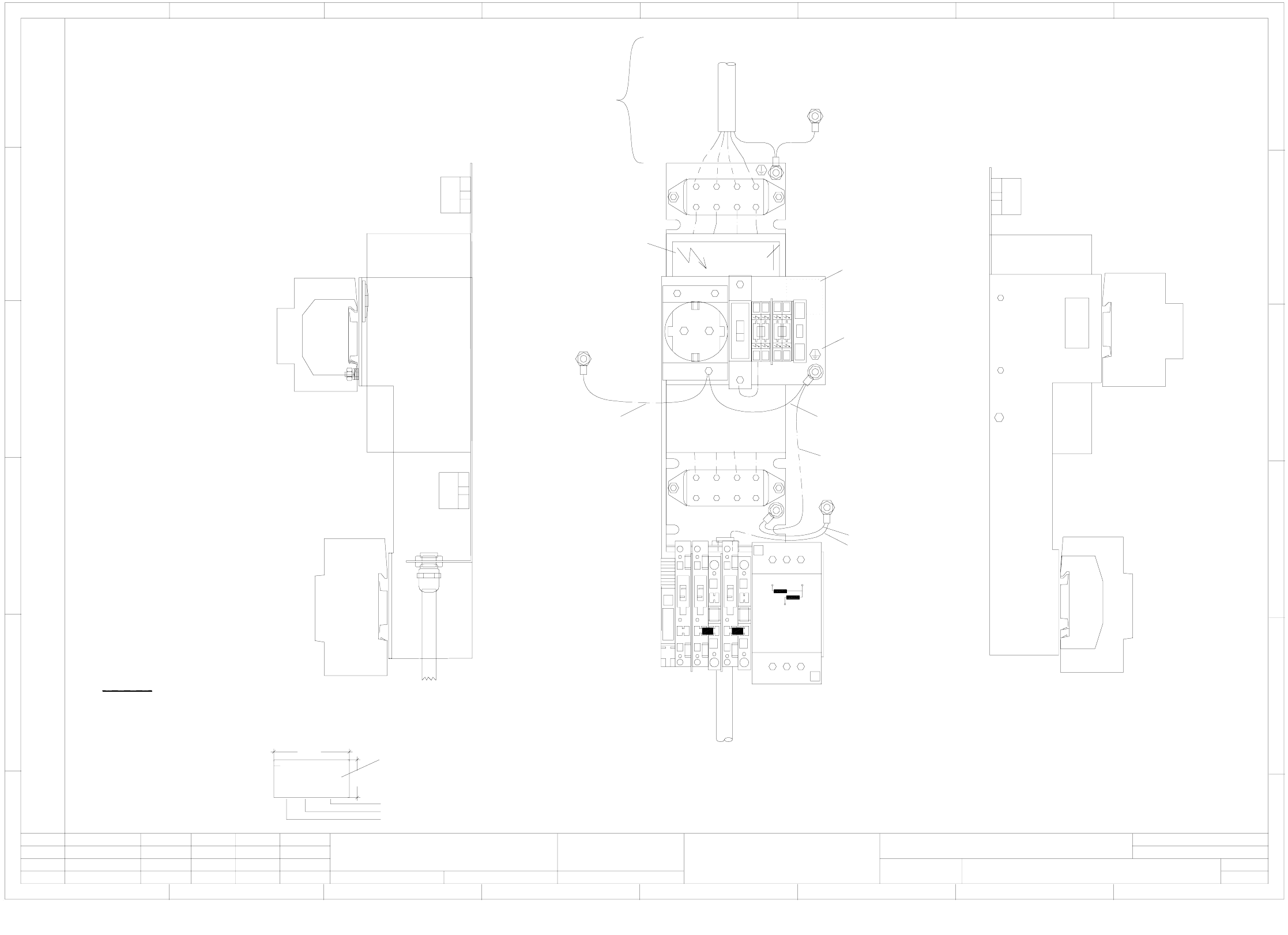
00300272-070101TD3 Discharge reactor and line filter
4567 8
1234567 8
A
B
C
D
E
F
123N
123N
N
A
B
C
D
E
F
12 3
L
PE
1
2
1
1
1
1
N
N
N
N
X216
* Note
Apply the following labels:
A: Identification label:
Font size 2.5mm, mat. Scotchal 3698-E (color: Al Ral 9006)
B: Warning label, type 206
C: Grounding label
SIEMENS
AA-BBBB-CCCC
00300272-FS
40
15
Function status as per current bill of material
Date (year/month/day) as per SN01007
Manufacturer/location as per SN37040
Serial number
A
Warning label (B)
Grounding label (C)
M4 grounding screw
Not part of the assembly
Adhesive base on
the back
5
X 217
3
2
1
4
4
2
1
Weitergabe sowie Vervielfältigung dieser Unterlage,Ver-
wertung und Mitteilung ihres Inhalts nicht gestattet, soweit
nicht ausdrücklich zugestanden. Zuwiderhandlungen ver-
pflichten zu Schadenersatz. Alle Rechte vorbehalten, ins
besondere für den Fall der Patenterteilung oder GM-Eintragung
Proprietary data, company confidential. All rights reserved.
Confie a titre de secret d´entreprise. Tous droits reserves.
Comunicado como segredo empresarial. Reservados todos os direilos.
Confiado como secrete industrial. Nos reservamos todos los derechos.
L&A EA1 R&D
SIEMENS
Check.
Author
Date
Stand.Status
1 .
7 .
1 .
Modified Date Name
Function status
Product status
Document status
06.03.2003
06.03.2003
06.03.2003
Tuth
Tuth
Tuth
Orig.
L&A EA1
Tuth
06.03.2003
Repl. f. Repl. by
00300272-070101TD3
Discharge reactor and line filter
SIPLACE S-27 HM
1
Sheet
Sh.
1
L&A
Assembly inscription as per inscription guide line 90010070-010101vd4
2
2
2
1
1
1
UW
V
SIEMENS
Discharge reactor
Z2
1234
Grounding
Machine frame
'To main power switch in the power supply unit
00342917-xx
To power plug
Grounding
Machine frame
00342916-xx (W1)
00342916-xx (W2)
00342916-xx (W3)
00342916-xx (W4)
00342916-xx (W5)
Grounding
U profile
Grounding
Angle support
Grounding
Line filter
(00356539-xx)
00342916-xx
4 - 2
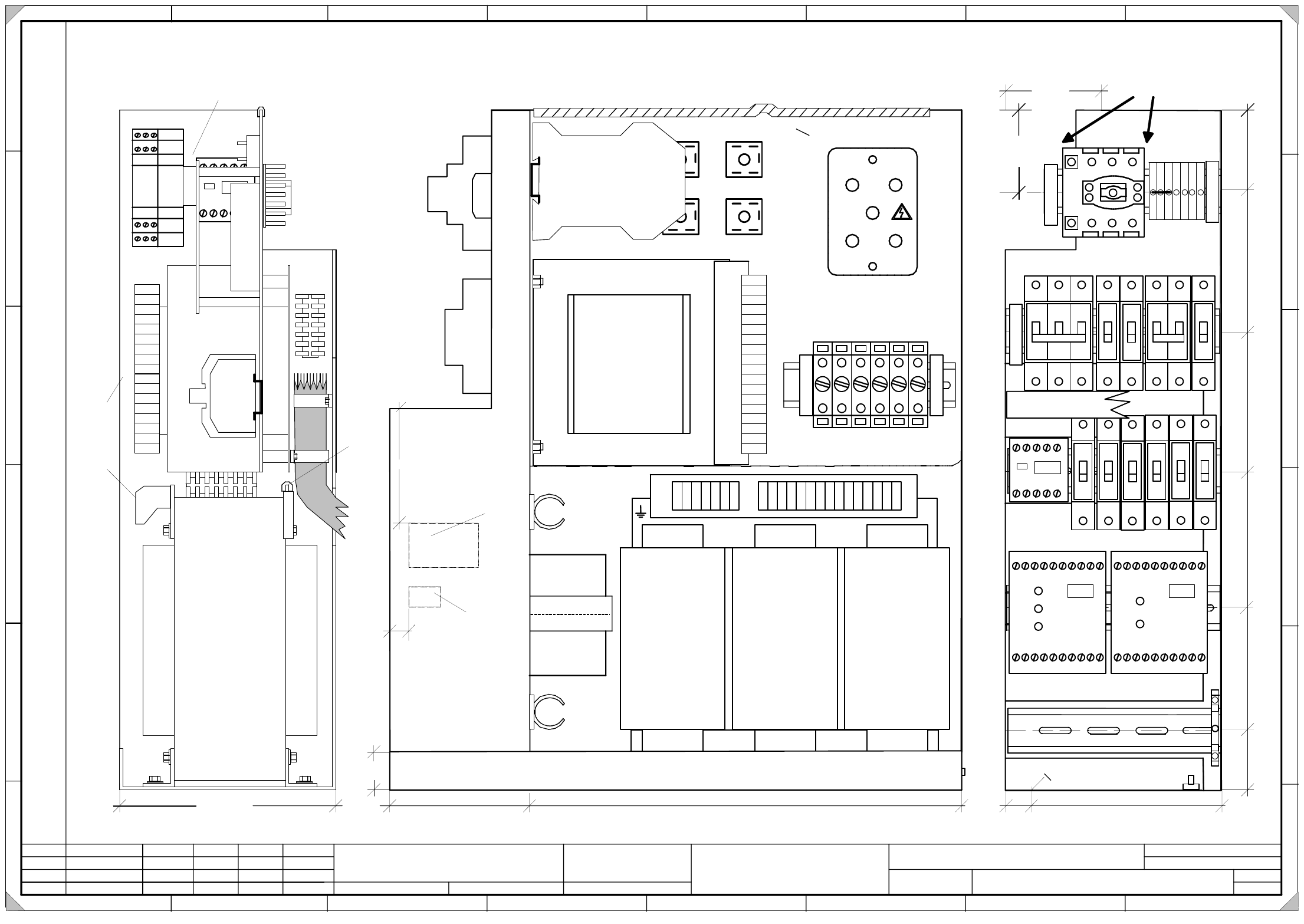
00336812-040101TD3 Power supply, structure, approx. up to serial no. 259 (sh. 1 of 2)
1.
4.
20.09.2002
20.09.2002
Tuth
Tuth 20.09.2002
Tuth
SMD placement system SIPLACE S-27 HM
Power supply, structure
approx. up to serial no. 259
00336812-040101TD3
20.09.2002 Tuth
1.
SIEMENS
L&A EA
Status Modified Date Name Standard Orig. Repl. f. Repl. by
Document. status
Product status
Function status Date
Author
Check.
Sheet
Sh.
W
e
i
t
e
r
g
a
b
e
s
o
w
i
e
V
e
r
v
i
e
l
f
ä
l
t
i
g
u
n
g
d
i
e
s
e
r
U
n
t
e
r
l
a
g
e
,
V
e
r
-
w
e
r
t
u
n
g
u
n
d
M
i
t
t
e
i
l
u
n
g
i
h
r
e
s
I
n
h
a
l
t
s
n
i
c
h
t
g
e
s
t
a
t
t
e
t
,
s
o
w
e
i
t
n
i
c
h
t
a
u
s
d
r
ü
c
k
l
i
c
h
z
u
g
e
s
t
a
n
d
e
n
.
Z
u
w
i
d
e
r
h
a
n
d
l
u
n
g
e
n
v
e
r
-
p
f
l
i
c
h
t
e
n
z
u
S
c
h
a
d
e
n
e
r
s
a
t
z
.
A
l
l
e
R
e
c
h
t
e
v
o
r
b
e
h
a
l
t
e
n
,
i
n
s
b
e
s
o
n
d
e
r
e
f
ü
r
d
e
n
F
a
l
l
d
e
r
P
a
t
e
n
t
e
r
t
e
i
l
u
n
g
o
d
e
r
G
M
-
E
i
n
t
r
a
g
u
n
g
P
r
o
p
r
i
e
t
a
r
y
d
a
t
e
,
c
o
m
p
a
n
y
c
o
n
f
i
d
e
n
t
i
a
l
.
A
l
l
r
i
g
h
t
s
r
e
s
e
r
v
d
.
C
o
n
f
i
e
a
t
i
t
r
e
d
e
s
e
c
r
e
t
d
´
e
n
t
r
e
p
r
i
s
e
.
T
o
u
s
d
r
o
i
t
s
r
e
s
e
r
v
e
s
.
C
o
m
u
n
i
c
a
d
o
c
o
m
o
s
e
g
r
e
d
o
e
m
p
r
e
s
a
r
i
a
l
.
R
e
s
e
r
v
a
d
o
s
t
o
d
o
s
o
s
d
i
r
e
i
l
o
s
.
C
o
n
f
i
a
d
o
c
o
m
o
s
e
c
r
e
t
e
i
n
d
u
s
t
r
i
a
l
.
N
o
s
r
e
s
e
r
v
a
m
o
s
t
o
d
o
s
l
o
s
d
e
r
e
c
h
o
s
.
A
B
C
D
E
F
1 2 3 4 5 6 7 8
1
2 3 4 5 6 7 8
A
B
C
D
E
F
1
U
1
1
V
1
1
W
1
1
U
3
1
V
3
1
W
3
1
N
2
U
1
2
V
1
2
W
1
3
U
3
3
V
3
3
W
3
3
U
1
3
V
1
3
W
1
4
U
1
4
V
1
4
W
1
4
N
1
2
A1 X1 X3 X5 13 23 33 43 57 65
A2 X2 X4 X6 14 24 34 44 58 66
K2
Ein
On
Frei
Ready
A1 X1 X3 X5 13 23 33 43 53 65
A2 X2 X4 X6 14 24 34 44 54 66
K1
Netz
Power
Kanal 1
Channel 1
Kanal 2
Channel 2
1
2
4
3
6
5
1
2
1
2
1
2
1
2
1
2
F1
F7 F8
F9 F10
F11
85mm
6
5
m
m
Make sure that the main switch can be
moved on the top hat rail for max. 2mm
to the left or to the right.
170
Cables must not protrude from the upper edge of the frame !
Edge protection
1
2
V3
V2
V4
V5
E
H
1
0
m
m
K3
246
135
N
N
16A
6A
6A
10A
6A 6A
A
B
I
d
e
n
t
i
f
i
c
a
t
i
o
n
l
a
b
e
l
I
n
s
p
e
c
t
i
o
n
l
a
b
e
l
X
2
0
0
N
N
N
P
E
P
E
P
E
P
E
1
2
1
2
1
2
F3 F4
F5
10A
6A20A
Inrush current limiter
A1
PE
1
2
3
5
6
6
8
9
10
11
11
13
14
1
2
F6
6A
7
12
4
170mm
PE
1
2
3
5
6
6
8
9
10
11
11
13
14
7
12
4
K4
V
4
V
5
A1
21,2
O6,0
0,0
13,0
167,0
270,0
370,0
470,0
535,0
T
S
3
5
l
=
1
6
0
T
S
3
5
l
=
1
4
6
T
S
3
5
l
=
1
4
6
T
S
3
5
l
=
1
6
4
T
S
3
5
l
=
1
3
0
Fit the clamp and use it as spacer.
Align K4 contactor with the right side!
C
o
n
n
e
c
t
i
o
n
s
m
u
s
t
n
o
t
p
r
o
t
r
u
d
e
f
r
o
m
t
h
e
t
e
r
m
i
n
a
l
s
!
T1
0,0 119,0 423,0 0,0
140
29,5
15
E
H
1
0
m
m
E
H
1
0
m
m
F
5
.
1
F
5
.
2
F
6
.
2
F
6
.
1
F
9
.
1
F
8
.
1
V1
1
2
4
3
F4.1
25A
T2
E
d
g
e
p
r
o
t
e
c
t
i
o
n
V
1
V1
K4
Fit wires A1 and K4 using cable ties.