S27HM Circuit Diagrams.pdf - 第92页
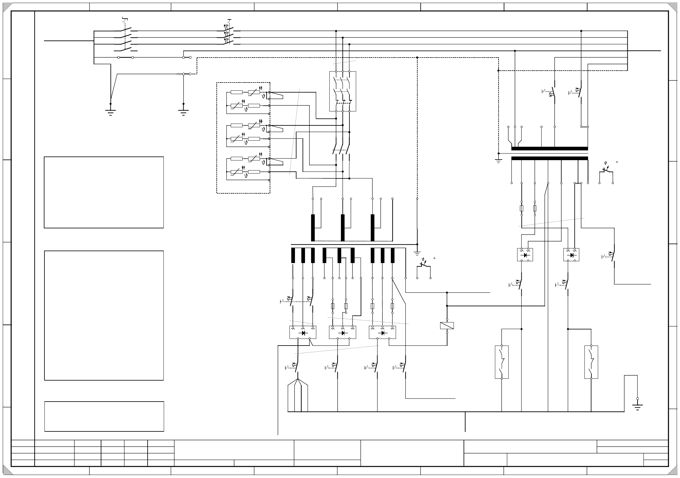
3 - 3 0033681 2-040 301LD3 Powe r supply , circui t diag ram a pprox. up to s erial no . 259 ( sh. 2 of 2) 1. 4. 05.11.2002 20.09.2002 Tut h Tut h 05.11.2002 Tut h SMD- Placement Sy stem S-27 HM Power supply circuit diag…
3 - 2
00336812-040301LD3 Power supply, circuit diagram approx. up to serial no. 259 (sh. 1 of 2)
1.
4.
05.11.2002
20.09.2002
Tuth
Tuth 05.11.2002
Tuth
SMD- Placement System S-27 HM
Power supply circuit diagram
approx. up to serial no. 259
00336812-040301LD3
20.09.2002 Tuth
3.
2
SIEMENS
L&A EA
Status Modified Date Name
Standard
Orig. Repl. f. Repl. by
Document status
Product status
Function status Date
Author
Checked
Sheet
Sh.
W
e
i
t
e
r
g
a
b
e
s
o
w
i
e
V
e
r
v
i
e
l
f
ä
l
t
i
g
u
n
g
d
i
e
s
e
r
U
n
t
e
r
l
a
g
e
,
V
e
r
-
w
e
r
t
u
n
g
u
n
d
M
i
t
t
e
i
l
u
n
g
i
h
r
e
s
I
n
h
a
l
t
s
n
i
c
h
t
g
e
s
t
a
t
t
e
t
,
s
o
w
e
i
t
n
i
c
h
t
a
u
s
d
r
ü
c
k
l
i
c
h
z
u
g
e
s
t
a
n
d
e
n
.
Z
u
w
i
d
e
r
h
a
n
d
l
u
n
g
e
n
v
e
r
-
p
f
l
i
c
h
t
e
n
z
u
S
c
h
a
d
e
n
e
r
s
a
t
z
.
A
l
l
e
R
e
c
h
t
e
v
o
r
b
e
h
a
l
t
e
n
,
i
n
s
b
e
s
o
n
d
e
r
e
f
ü
r
d
e
n
F
a
l
l
d
e
r
P
a
t
e
n
t
e
r
t
e
i
l
u
n
g
o
d
e
r
G
M
-
E
i
n
t
r
a
g
u
n
g
P
r
o
p
r
i
e
t
a
r
y
d
a
t
e
,
c
o
m
p
a
n
y
c
o
n
f
i
d
e
n
t
i
a
l
.
A
l
l
r
i
g
h
t
s
r
e
s
e
r
v
d
.
C
o
n
f
i
e
a
t
i
t
r
e
d
e
s
e
c
r
e
t
d
´
e
n
t
r
e
p
r
i
s
e
.
T
o
u
s
d
r
o
i
t
s
r
e
s
e
r
v
e
s
.
C
o
m
u
n
i
c
a
d
o
c
o
m
o
s
e
g
r
e
d
o
e
m
p
r
e
s
a
r
i
a
l
.
R
e
s
e
r
v
a
d
o
s
t
o
d
o
s
o
s
d
i
r
e
i
l
o
s
.
C
o
n
f
i
a
d
o
c
o
m
o
s
e
c
r
e
t
e
i
n
d
u
s
t
r
i
a
l
.
N
o
s
r
e
s
e
r
v
a
m
o
s
t
o
d
o
s
l
o
s
d
e
r
e
c
h
o
s
.
A
B
C
D
E
F
1 2 3 4 5 6 7 8
1
2 3 4 5 6 7 8
A
B
C
D
E
F
1
2
K4
3
4
5
6
150VDC
G
N
D
13 23 33
14 24 34
K1
11
12
13
14
21
22
23
24
31
32
33
34
56R 25R
25R 56R
56R 25R
25R 56R
56R 25R
25R 56R
+-
A1(+)
A2(-)
1
1
L
+
(
b
k
)
2
1
L
+
(
b
k
)
1
1
1
L
+
(
b
k
)
4
1
L
+
(
b
k
)
3
2
L
+
(
b
k
)
1
U
1
1
U
3
2
U
1
2
V
1
2
W
1
4
N
P
E
400 204
1
V
1
1
V
3
400 204
1
W
1
1
W
3
400 204
1
N
105 105 105
3
V
1
3
V
3
3
W
1
68 48 68
4
U
1
4
V
1
4
W
1
42 4242 0
6x =130
1
2
0
3
W
3
48
3
U
1
3
U
3
68 48
+-
K4
5
3
L
+
(
b
k
)
1
L
-
0
0
3
2
4
3
5
8
-
x
x
70/100VDC 24VDC
1
0
q
m
m
Emerg.-stop, ext. 24VAC.
To sheet 2
Not-Aus int. 24VAC.
zTo sheet 2
A
W
G
1
2
b
k
AWG14
AWG12 bk
bk 0,75qmm
AWG14
7
6
L
+
(
b
k
)
8
2
L
-
(
b
k
)
9
5
L
+
(
b
k
)
6
4
L
+
(
b
k
)
1
0
7
L
+
(
b
k
)
AWG16 sw
A1
6A
1
2
F8
10A
1
2
F9
6A
1
2
F5
6A
1
2
F6
6A
1
2
F7
20A
1
2
F4
Grundgestell Stromversorgung
2
1
3
gegn
Inrush current limiter
1
2
3
4
5
6
7
8
9
AWG16
bk
T2
V1 V2 V3
V4 V5
T1
00356733-xx
To terminal panel
To terminal panel
If the machine is operated with 208/120V (USA),
make sure to:
1.) connect the inrush current limiter A1 in parallel.
(i.e. disconnect wire 3 from 13 and connect it to 14,
disconnect wire 2 from 12 and connect it to 13.
For the other phases, apply this system as
appropriate.)
2.) Reconnect transformer T1 infeed from 230 to 120V
transformer T2 infeed (1), (2), (3) from 400
to 208.
Link circuit Lifting table/star Tape cutter
GND 30/34VDC
dp/Z axes
10VDC
Star, slow motion
30/34VDC
Width adjustment
10VDC
spare
00356539-xx
To sheet 2 K2:A2
Erdungsbolzen
X200:PE
AWG14 bk
Frontabdeckung
0
0
3
4
1
1
9
3
-
x
x
y
e
g
n
X
2
0
0
:
P
E
T1L1
Q1
T2L2
T3
L3
N´
N
N
N
4
16 A
56
F1
34
12
(2)
(1)
(3)
(6)
Wiring instructions !
(
1
)
(
2
)
(
3
)
(
1
)
(
2
)
Warning! Power supply!
When operating the machine with a modular
conveyor system (S27 HM) make sure to:
- reconnect the conductors (1) and (2) at
transformer
T1
in the following way:
wire (1) from terminal 7 to terminal 13
wire (2) from terminal 11 to terminal 12
This ensures, that a voltage (6L+) of
34VDC is available at F9.
- reconnect the conductors (4), (5), and (6) at
transformer
T2
in the following way:
wire (4) from terminal 3U3 to terminal 3U1
wire (5) from terminal 3V3 to terminal 3V1
wire (6) from terminal 3W3 to terminal 3W1
This ensures the a voltage (2L+) of
100VDC is available at F5.
(
4
)
(
5
)
(
6
)
10A
1
2
F3
6A
2
1
F11
+-
0
1
0
2
4
2
8
1
0
2
4
2
8
2
3
0
1
5
0
1
2
0
0
+
5
%
-
5
%
123 45 66
7813 9 10
12
11
6x =130
14 15
6A
1
2
F10
13
14
K2
23
24
K2
(5)
(4)
gnye
bn
bk
wh
bl
rd
gy
(2)
(1)
(3)
(6)
bn
bk
wh
bl
X200:N
Route the N conductor via the
main power switch. (IT net)
e.g. France / Italy / USA
Warning! Machine type!
00342917-xx(W3)
To main power filter
Main power switch
1
00357898-xx
+-+-
The wiring in this circuit diagram
corresponds to the state of delivery
of the power supply unit.
1
0
A
T
1
2
F
5
.
1
1
0
A
T
1
2
F
5
.
2
1
0
A
T
1
2
F
6
.
1
1
0
A
T
1
2
F
6
.
2
bk AWG14
1
0
A
T
1
2
F
9
.
1
1
0
A
T
1
2
F
8
.
1
25A
1
2
F4.1
3
4
A note regarding fine-wire fuses !
Always check the fine-wire fuses F5.1, F5.2
or F6.1, F6.2 or F8.1 or F9.1, when any of the
automatic circuit breakers F5, F6, F8 or F9
has tripped.
Please note !
Make sure that the leads to the inrush
current limiter A1 are long enough and
run them in a way that they can easily be
reconnected.
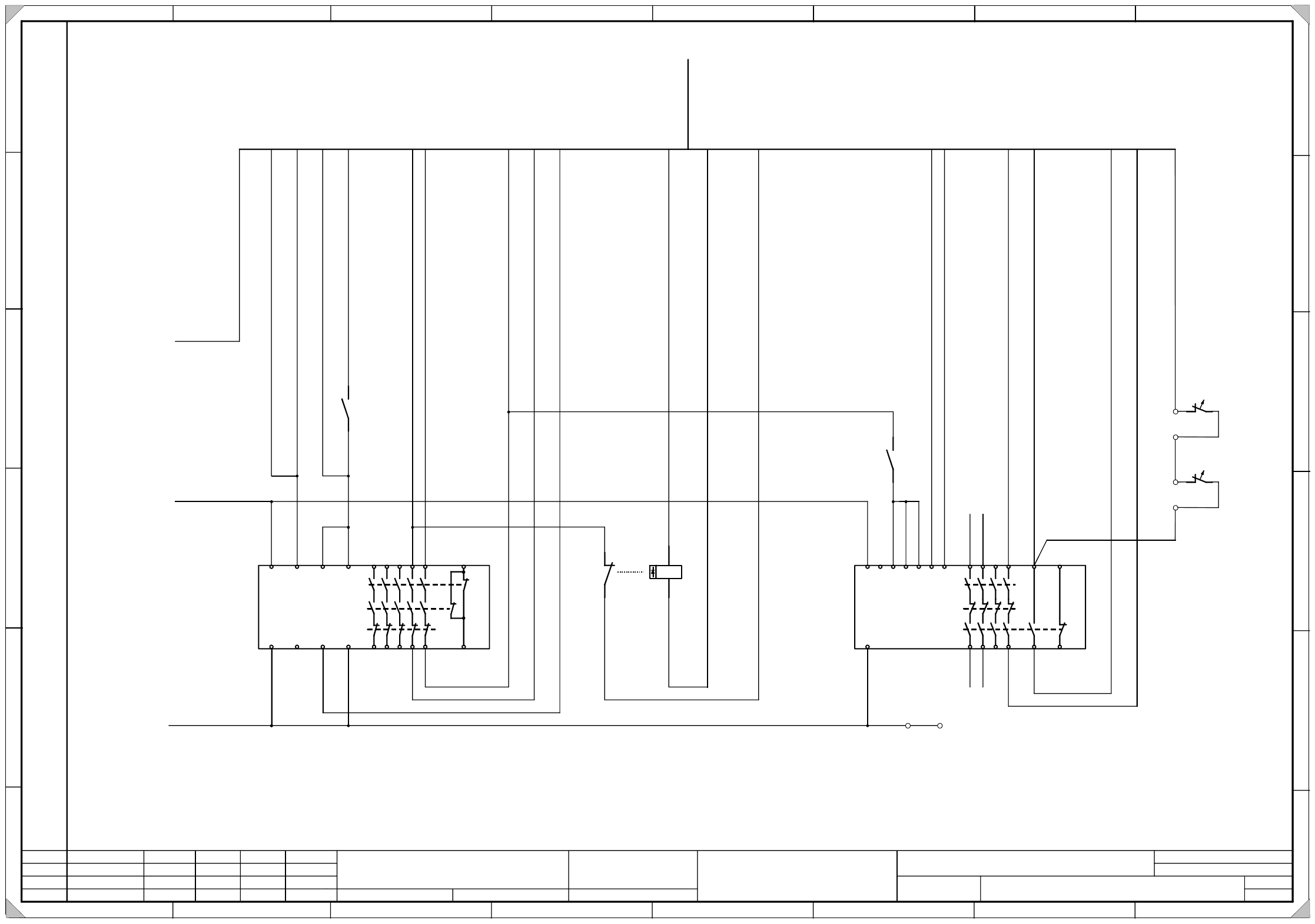
3 - 3
00336812-040301LD3 Power supply, circuit diagram approx. up to serial no. 259 (sh. 2 of 2)
1.
4.
05.11.2002
20.09.2002
Tuth
Tuth 05.11.2002
Tuth
SMD- Placement System S-27 HM
Power supply circuit diagram
approx. up to serial no. 259
00336812-040301LD3
20.09.2002 Tuth
3.
2
SIEMENS
L&A EA
Status Modified Date Name
Standard
Orig. Repl. f. Repl. by
Document status
Product status
Function status Date
Author
Checked
Sheet
Sh.
W
e
i
t
e
r
g
a
b
e
s
o
w
i
e
V
e
r
v
i
e
l
f
ä
l
t
i
g
u
n
g
d
i
e
s
e
r
U
n
t
e
r
l
a
g
e
,
V
e
r
-
w
e
r
t
u
n
g
u
n
d
M
i
t
t
e
i
l
u
n
g
i
h
r
e
s
I
n
h
a
l
t
s
n
i
c
h
t
g
e
s
t
a
t
t
e
t
,
s
o
w
e
i
t
n
i
c
h
t
a
u
s
d
r
ü
c
k
l
i
c
h
z
u
g
e
s
t
a
n
d
e
n
.
Z
u
w
i
d
e
r
h
a
n
d
l
u
n
g
e
n
v
e
r
-
p
f
l
i
c
h
t
e
n
z
u
S
c
h
a
d
e
n
e
r
s
a
t
z
.
A
l
l
e
R
e
c
h
t
e
v
o
r
b
e
h
a
l
t
e
n
,
i
n
s
b
e
s
o
n
d
e
r
e
f
ü
r
d
e
n
F
a
l
l
d
e
r
P
a
t
e
n
t
e
r
t
e
i
l
u
n
g
o
d
e
r
G
M
-
E
i
n
t
r
a
g
u
n
g
P
r
o
p
r
i
e
t
a
r
y
d
a
t
e
,
c
o
m
p
a
n
y
c
o
n
f
i
d
e
n
t
i
a
l
.
A
l
l
r
i
g
h
t
s
r
e
s
e
r
v
d
.
C
o
n
f
i
e
a
t
i
t
r
e
d
e
s
e
c
r
e
t
d
´
e
n
t
r
e
p
r
i
s
e
.
T
o
u
s
d
r
o
i
t
s
r
e
s
e
r
v
e
s
.
C
o
m
u
n
i
c
a
d
o
c
o
m
o
s
e
g
r
e
d
o
e
m
p
r
e
s
a
r
i
a
l
.
R
e
s
e
r
v
a
d
o
s
t
o
d
o
s
o
s
d
i
r
e
i
l
o
s
.
C
o
n
f
i
a
d
o
c
o
m
o
s
e
c
r
e
t
e
i
n
d
u
s
t
r
i
a
l
.
N
o
s
r
e
s
e
r
v
a
m
o
s
t
o
d
o
s
l
o
s
d
e
r
e
c
h
o
s
.
A
B
C
D
E
F
1 2 3 4 5 6 7 8
1
2 3 4 5 6 7 8
A
B
C
D
E
F
A1(+)
A2(-)
21
22
K3
13
14
K3
43
44
K3
g
r
w
h
b
n
g
n
b
l
w
h
/
g
n
b
k
v
i
b
n
/
g
n
y
e
w
h
/
g
y
g
y
/
b
n
p
k
/
b
r
g
y
/
p
k
r
d
/
b
l
w
h
/
y
e
y
e
/
b
n
S
h
e
e
t
1
7
/
E
Sheet 1 7/E
r
d
p
k
0
0
3
2
1
1
1
3
-
x
x
MP1
T
o
e
x
t
e
r
n
a
l
e
m
e
r
g
.
-
s
t
o
p
c
i
r
c
u
i
t
2
4
V
A
C
2
4
V
A
C
T
o
O
n
b
u
t
t
o
n
F
r
o
m
e
m
e
r
g
.
-
s
t
o
p
c
i
r
c
u
i
t
2
4
V
D
C
F
r
o
m
e
m
e
r
g
.
-
s
t
o
p
c
i
r
c
u
i
t
T
o
k
e
y
s
w
i
t
c
h
T
o
s
i
g
n
a
l
i
n
g
c
i
r
c
u
i
t
,
c
o
n
t
r
o
l
O
n
F
r
o
m
O
n
b
u
t
t
o
n
F
r
o
m
s
i
g
n
a
l
i
n
g
c
i
r
c
u
i
t
,
s
o
f
t
w
a
r
e
E
n
a
b
l
e
S
o
f
t
w
a
r
e
E
n
a
b
l
e
S
o
f
t
w
a
r
e
E
n
a
b
l
e
T
o
O
n
b
u
t
t
o
n
F
r
o
m
O
n
b
u
t
t
o
n
5
0
V
D
C
E
n
a
b
l
e
+
2
4
V
D
C
S
i
g
n
a
l
i
n
g
c
i
r
c
u
i
t
,
i
n
p
u
t
5
0
V
D
C
E
n
a
b
l
e
To sheet 1
F10:2 24V AC
To sheet 1
GND
To sheet 1
F7:2 24V AC
AWG 16bk
AWG 16bk
K1 K2
M
14
15
T1
1
2
T2
w
h
/
p
k
bk 0.75
T
e
m
p
e
r
a
t
u
r
e
m
o
n
i
t
o
r
i
n
g
T
1
a
n
d
T
2
Temperature switch
2
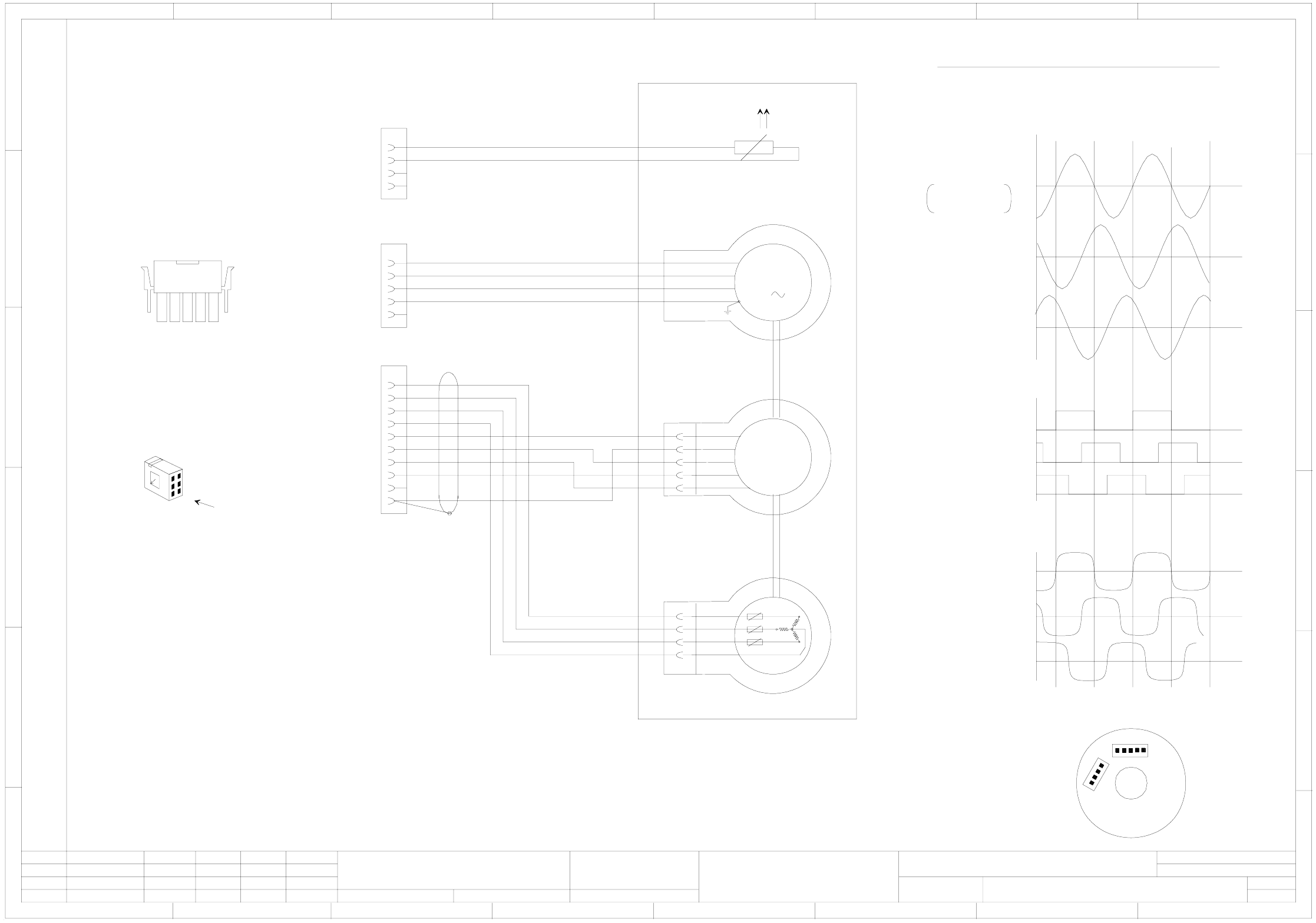
3 - 4
00337065-060101LD3 X motor, S-27 HM
besondere für den Fall der Patenterteilung oder GM-Eintragung
pflichten zu Schadenersatz. Alle Rechte vorbehalten, ins
nicht ausdrücklich zugestanden. Zuwiderhandlungen ver-
wertung und Mitteilung ihres Inhalts nicht gestattet, soweit
Weitergabe sowie Vervielfältigung dieser Unterlage,Ver-
Confiado como secrete industrial. Nos reservamos todos los derechos.
Comunicado como segredo empresarial. Reservados todos os direilos.
Confie a titre de secret d´entreprise. Tous droits reserves.
Proprietary data, company confidential. All rights reserved.
L&A
SIEMENS
Date
Author
Check.
Stand.Status
6 .
1 .
1 .
NameDateModified
Function status
Product status
Document status
01.10.2002
14.09.1999
14.09.1999
Tuth
Tuth
Tuth
Orig.
L&A EA
01.10.2002
Tuth
Repl. byRepl. f.
00337065-060101LD3
X motor S-27 HM
SIPLACE S-27 HM
1
Sheet
Sh.
1
78
1234567 8
A
B
C
D
E
F
RSE U (X13.5)
RSE V (X13.6)
RSE W (X13.7)
RSE against RSE GND (X13.10)
Tachom. U (X13.1)
Tachom. V (X13.2)
Tachom. W (X13.3)
U (X3.1) against V (X3.2)
Test probe at U
Ground at V
V (X3.2) against W (X3.3)
W (X3.3) against U (X3.1)
e.m.f. motor
Tachom. against tachom. TP (X13.4)
Calibration of the tachometer/RSE unit for the stator winding
All signals are shown by clockwise rotation (looking at the driving shaft).
Cable side
Inscription label as illustrated.
1FT3035-6AZ99-9
A
B
C
D
E
F
12 3 4 5 6
1
ye
rd
bk
gnye
M
3
2
3
4
5
ye
rd
bk
gnye
X3**
00337065-xx (W1)
5
RSE
4
3
2
1
XR
4
3
2
1
XT
NTC / 2K
Tachom.
1
2
3
4
5
ye
rd
wh
gn
6
7
8
9
10
vi
wh/bk
wh/bn
bn
or
ye
wh
gn
bn
or
vi
wh/bn
wh/bk
rd
Connect the shielding to pin 10
X13**
00337065-xx (W2)
1
2
3
4
gy
gy
X14**
PTC
Cold-state resistance of the temperature sensor < 100Ohm
Temp. sensor
Temp. sensor
Key
Spare
Mot. U
Mot. V
Mot. W
Mot. PE
Spare
00337065-xx (W3)
Tachom. U
Tachom. V
Tachom. W
Tachom. TP
RSE. U
RSE. V
RSE. W
RSE. +5V
Key
RSE GND
2
4
6
1
3
5
MATE-N-LOK plug casing
For details concerning the inscription and design of the labels, please refer to the inscription guidelines for cable sets which you will find included in the bill of materials.
Refer to drawing 00337065-xx-xx-xx VD3 for the conductor lengths and the location of the inscription labels.
XR
1
XT
1
View onto tachometer board
An NTC resistor of 2 KOhms is connected in series with each tachometer winding.
NTC type: S 867/2K/+140
Epcos order no.: B57867-S202-+140
The numerical sequence of a locking-clip plug is as viewed from the rear side of the casing.