S27HM Circuit Diagrams.pdf - 第125页
4 - 1 1 0035621 3-020 101 TD3 S-27 H M contro l unit , basic m odule ( viewed fr om the back) (sh. 2 o f 2) PE PWD X18 X19 X17 XB51su P24 GND SENSE+ X21 X20 SENSE- DC-GOOD GND P24 VCC GND GND VCC P12 N12 P15 N15 XA12s u …
4 - 10
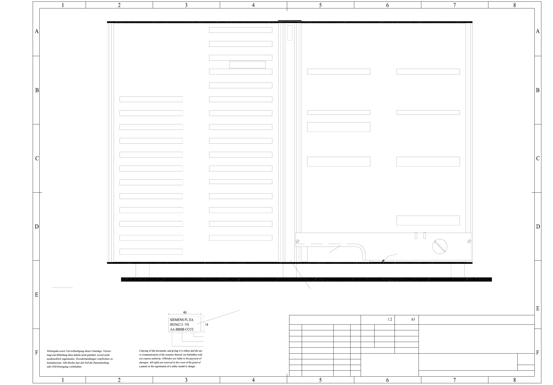
00356213-020101TD3 S-27 HM control unit, basic module (viewed from the front) (sh. 1 of 2)
XB50su
XA12su
XA11su
XA10su
XA9su
XA8su
XA7su
XA6su
XA5su
XA4su
XA3su
XA2su
XA1su
XL4su
XL3su
XL2su
XL1su
XD1su
XC4su
XC3su
XC2su
XC1su
XB7su
XB6su
XB5su
XB4su
XB3su
XB2su
XB1su
UBAT+UBAT-
XK3su
XK2su
XH1su
XG8su
XK1su
XH2su
XG9su
XM1su
X1ue
001
003
2
07.03.01
00356213-020101TD3
US01
FS02 10527
Tek
Tek
28.06.00
07.03.01
Tekin28.06.2000
1
FSUAUSESFS
SIEMENS
L&A EA
* Please note
Fit the following labels on the inside (flush with the front plate) :
A: identification label
Font size 2.5mm, material Scotchal 3698-E (color Al RAL 9006)
Assembly inscription acc. to VA-F-510-001
Function status (FS) in compliance with the current parts list
Retaining bar
Edge protection
* Please note
Combination backplane A32
Identification: testing engineer, month, yearB: inspection label
Date (year/month/day) acc. to SN 01007
Series number
Manufacturer/location acc. to SN 37040
Status Modified Date Name
Scale
Format
Date
Name
Author
Check.
Stand.
Main no.
(Drawing number)
S-27 HM control unit, basic module
( viewed from the front )
Sheet
Sh.
SIPLACE S-27 HM SMD Placement System
Battery
3.8V
New
Fan unit Assembly A35 ( ue )
4 - 11
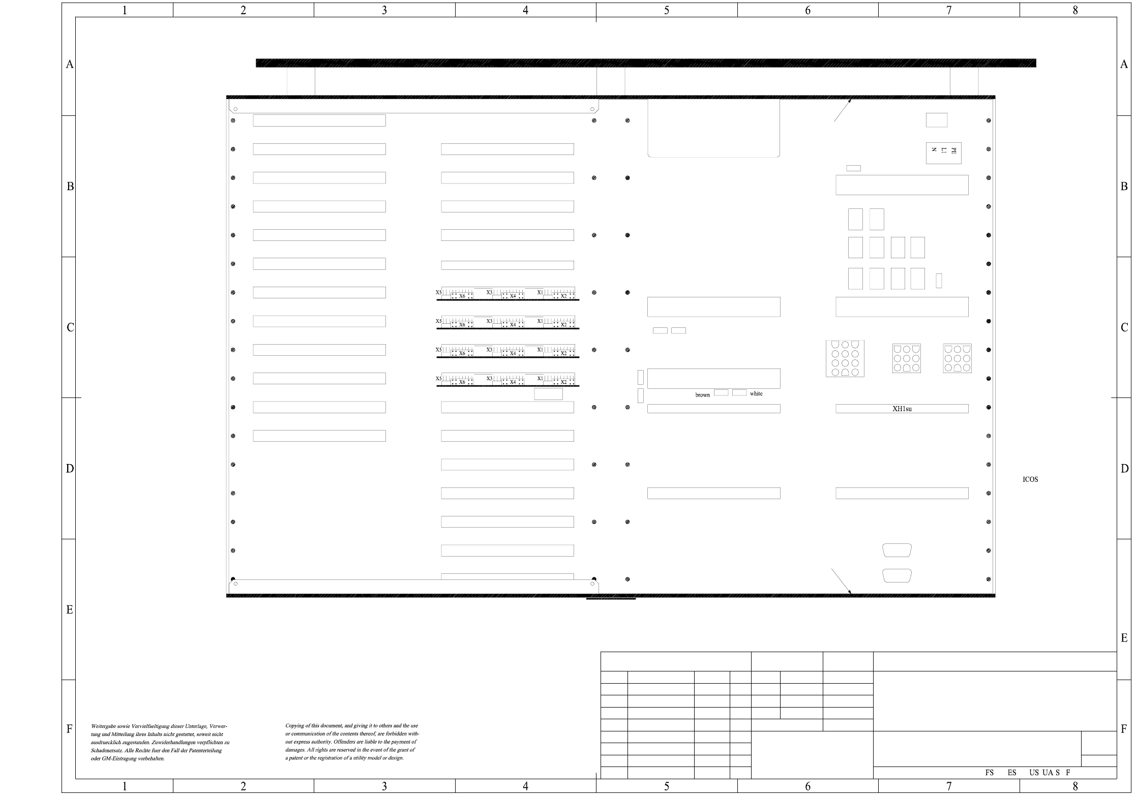
00356213-020101TD3 S-27 HM control unit, basic module (viewed from the back) (sh. 2 of 2)
PE
PWD
X18X19
X17
XB51su
P24
GND
SENSE+
X21
X20
SENSE-
DC-GOOD
GND
P24
VCC
GND
GND
VCC
P12
N12
P15
N15
XA12su
XA11su
XA10su
XA9su
XA8su
XA7su
XA6su
XA5su
XA4su
XA3su
XA2su
XA1su
XL4su
XL3su
XL2su
XL1su
XD1su
XB7su
XB6su
XB5su
XB4su
XB3su
XB2su
XK3su
XK2su
XG8su
XK1su
XH2su
XG9su
XM1su
001
2
A3
07.03.01
00356213-020101TD3
US01
FS02
neu
10527
Tek
Tek
28.06.00
07.03.01
Tekin28.06.2000
1:2
2
SIEMENS
L&A EA
GEM machine controller
Winchester/Floppy GEM
Spare
Spare
Spare
Winchester/Floppy
Axis board 1 x AC
Machine controller
Axis board 1 x AC
Communications assembly
Axis board
Axis board
I/O board
Spare
I/O board
I/O board
Spare
Combination backplane A32
Fit the combination backplane A32 first! Then fit the protective cover 002.
Fan unit
Ground point
Ground point
Video multiplexer
A30 assembly (ud)
A29 assembly (uc)
A28 assembly (ta)
A27 assembly (sz)
Status Modified Date Name
Scale
Format
Date
Name
Stand.
Check.
Author
(Drawing number)
Main no.
( viewed from the back )
Control unit S-27 HM, basic module
SIPLACE S-27 HM SMD Placement System
Sheet
Sh.
4 - 12
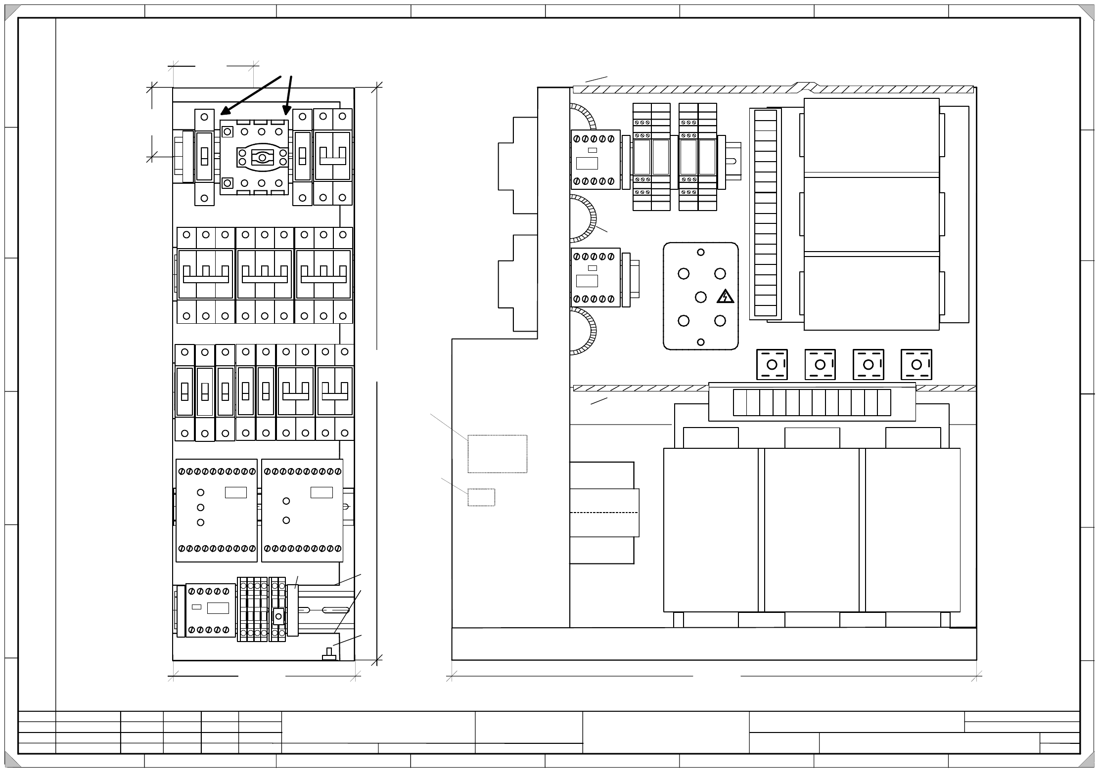
00356395-040201TD3 Power supply, electrical design, Option for Japan,
approx. up to serial no. 259 (sh. 1 of 2)
1.
4.
21.08.2001
26.06.2001
Tuth
Tuth 26.06.2001
Tuth
Siplace S-27 HM Placement System
Power supply, electrical design,
Option for Japan
approx. up to serial no. 259
00356395-040201TD3
08.02.2001 Tuth
2.
SIEMENS
L&A EA
Status Modified Date Name Standard Orig. Repl.f. Repl. by
Document status
Product status
Function status Date
Author
Check.
Sheet
Sh.
W
e
i
t
e
r
g
a
b
e
s
o
w
i
e
V
e
r
v
i
e
l
f
ä
l
t
i
g
u
n
g
d
i
e
s
e
r
U
n
t
e
r
l
a
g
e
,
V
e
r
-
w
e
r
t
u
n
g
u
n
d
M
i
t
t
e
i
l
u
n
g
i
h
r
e
s
I
n
h
a
l
t
s
n
i
c
h
t
g
e
s
t
a
t
t
e
t
,
s
o
w
e
i
t
n
i
c
h
t
a
u
s
d
r
ü
c
k
l
i
c
h
z
u
g
e
s
t
a
n
d
e
n
.
Z
u
w
i
d
e
r
h
a
n
d
l
u
n
g
e
n
v
e
r
-
p
f
l
i
c
h
t
e
n
z
u
S
c
h
a
d
e
n
e
r
s
a
t
z
.
A
l
l
e
R
e
c
h
t
e
v
o
r
b
e
h
a
l
t
e
n
,
i
n
s
b
e
s
o
n
d
e
r
e
f
ü
r
d
e
n
F
a
l
l
d
e
r
P
a
t
e
n
t
e
r
t
e
i
l
u
n
g
o
d
e
r
G
M
-
E
i
n
t
r
a
g
u
n
g
P
r
o
p
r
i
e
t
a
r
y
d
a
t
e
,
c
o
m
p
a
n
y
c
o
n
f
i
d
e
n
t
i
a
l
.
A
l
l
r
i
g
h
t
s
r
e
s
e
r
v
d
.
C
o
n
f
i
e
a
t
i
t
r
e
d
e
s
e
c
r
e
t
d
´
e
n
t
r
e
p
r
i
s
e
.
T
o
u
s
d
r
o
i
t
s
r
e
s
e
r
v
e
s
.
C
o
m
u
n
i
c
a
d
o
c
o
m
o
s
e
g
r
e
d
o
e
m
p
r
e
s
a
r
i
a
l
.
R
e
s
e
r
v
a
d
o
s
t
o
d
o
s
o
s
d
i
r
e
i
l
o
s
.
C
o
n
f
i
a
d
o
c
o
m
o
s
e
c
r
e
t
e
i
n
d
u
s
t
r
i
a
l
.
N
o
s
r
e
s
e
r
v
a
m
o
s
t
o
d
o
s
l
o
s
d
e
r
e
c
h
o
s
.
A
B
C
D
E
F
1 2 3 4 5 6 7 8
1
2 3 4 5 6 7 8
A
B
C
D
E
F
1
2
L1 X1 X3 X5 13 23 33 43 57 65
L2 X2 X4 X6 14 24 34 44 58 66
K2
Ein
On
Frei
Ready
L1 X1 X3 X5 13 23 33 43 53 65
L2 X2 X4 X6 14 24 34 44 54 66
K1
Netz
Power
Kanal 1
Channel 1
Kanal 2
Channel 2
1
2
4
3
6
51
2
4
3
6
51
2
4
3
6
5
1
2
4
3
1
2
4
3
1
2
1
2
4
31
2
1
2
1
2
1
2
1
2
F10
F7
F11
F1 F2 F3
F4 F5
F6 F8
F9 F12 F13
85mm
6
5
m
m
On the top hat rail, the main switch
must have a play of max. 2mm on each side!
5
3
5
m
m
170mm
G
r
o
u
n
d
b
o
l
t
Cables must not protrude from the upper edge of the frame !
K4
490mm
Edge protection
14 24 34
12 22 32
13 23 33
11 21 31
14 24 34
12 22 32
13 23 33
11 21 31
1
2
V3
V1
V2 V4 V5
A1 A2
Edge protection
E
H
6
-
1
0
m
m
E
d
g
e
p
r
o
t
e
c
t
i
o
n
E
H
1
0
m
m
E
H
6
-
1
0
m
m
E
H
6
-
1
0
m
m
Edge protection
K5
E
H
6
m
m
K3
P
E
P
E
P
E
P
E
M
M
X
2
0
0
EH10mm
246
135
N
N
E
H
6
-
1
0
m
m
6A
6A 6A
10A
16A 16A
20A
6A
6A
6A 10A
6A
6A
A
B
A
.
I
d
e
n
t
i
f
i
c
a
t
i
o
n
l
a
b
e
l
B
.
I
n
s
p
e
c
t
i
o
n
l
a
b
e
l