S27HM Circuit Diagrams.pdf - 第120页
4 - 6 0035447 5-010 201 TD3 Servo u nit, ov erview ( sh. 2 o f 2) SIEMENS AG L&A E A Status Modified D atum Name Stand. Orig . Repl. f. Repl. by Docume nt. s tatus Product status Function status Date Author Check. Sh…
4 - 5
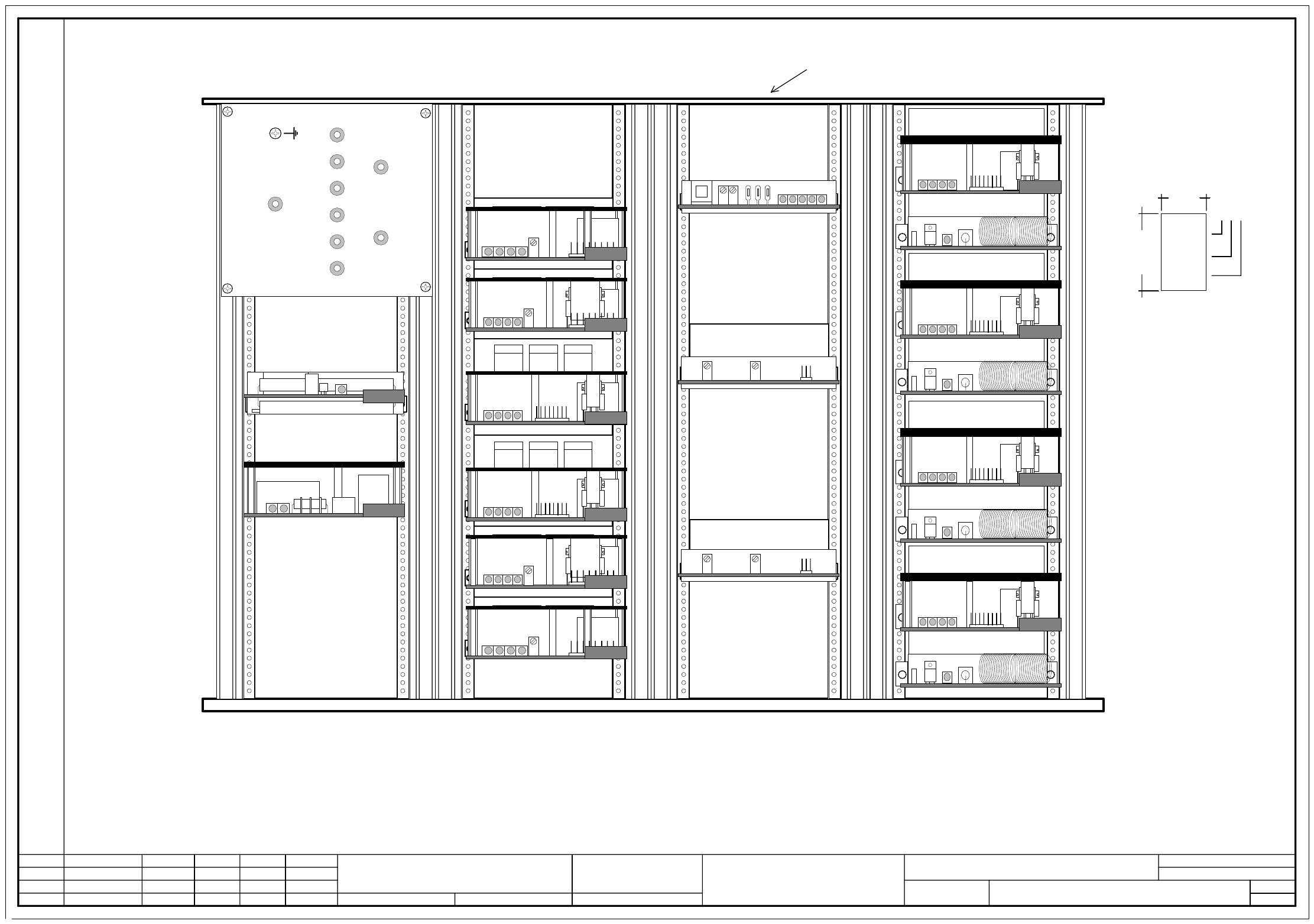
00354475-010201TD3 Servo unit, overview (sh. 1 of 2)
SIEMENS AGL&A EA
Status Modified Datum Name Stand. Orig. Repl. f. Repl. by
Document. status
Product status
Function status Date
Author
Check.
Sheet
Sh.
W
e
i
t
e
r
g
a
b
e
s
o
w
i
e
V
e
r
v
i
e
l
f
ä
l
t
i
g
u
n
g
d
i
e
s
e
r
U
n
t
e
r
l
a
g
e
,
V
e
r
-
w
e
r
t
u
n
g
u
n
d
M
i
t
t
e
i
l
u
n
g
i
h
r
e
s
I
n
h
a
l
t
s
n
i
c
h
t
g
e
s
t
a
t
t
e
t
,
s
o
w
e
i
t
n
i
c
h
t
a
u
s
d
r
ü
c
k
l
i
c
h
z
u
g
e
s
t
a
n
d
e
n
.
Z
u
w
i
d
e
r
h
a
n
d
l
u
n
g
e
n
v
e
r
-
p
f
l
i
c
h
t
e
n
z
u
S
c
h
a
d
e
n
e
r
s
a
t
z
.
A
l
l
e
R
e
c
h
t
e
v
o
r
b
e
h
a
l
t
e
n
,
i
n
s
b
e
s
o
n
d
e
r
e
f
ü
r
d
e
n
F
a
l
l
d
e
r
P
a
t
e
n
t
e
r
t
e
i
l
u
n
g
o
d
e
r
G
M
-
E
i
n
t
r
a
g
u
n
g
P
r
o
p
r
i
e
t
a
r
y
d
a
t
e
,
c
o
m
p
a
n
y
c
o
n
f
i
d
e
n
t
i
a
l
.
A
l
l
r
i
g
h
t
s
r
e
s
e
r
v
d
.
C
o
n
f
i
e
a
t
i
t
r
e
d
e
s
e
c
r
e
t
d
´
e
n
t
r
e
p
r
i
s
e
.
T
o
u
s
d
r
o
i
t
s
r
e
s
e
r
v
e
s
.
C
o
m
u
n
i
c
a
d
o
c
o
m
o
s
e
g
r
e
d
o
e
m
p
r
e
s
a
r
i
a
l
.
R
e
s
e
r
v
a
d
o
s
t
o
d
o
s
o
s
d
i
r
e
i
l
o
s
.
C
o
n
f
i
a
d
o
c
o
m
o
s
e
c
r
e
t
e
i
n
d
u
s
t
r
i
a
l
.
N
o
s
r
e
s
e
r
v
a
m
o
s
t
o
d
o
s
l
o
s
d
e
r
e
c
h
o
s
.
2.
1.
1.
25.05.2000
20.03.2002
25.05.2000
Tuth
Tuth
Tuth 04.05.2001
Tuth
00354475-010201TD3
SMD placement system Siplace S-27 HM
Servo unit, overview
S
i
e
m
e
n
s
P
L
E
A
1
A
A
-
B
B
B
B
-
C
C
C
C
M
a
t
.
N
r
.
0
0
3
5
4
4
7
5
-
0
1
4
0
m
m
1
8
m
m
S
e
r
i
e
s
n
u
m
b
e
r
D
a
t
e
(
y
e
a
r
/
m
o
n
t
h
/
d
a
y
)
a
c
c
.
t
o
S
N
0
1
0
0
7
M
a
n
u
f
a
c
t
u
r
e
r
/
l
o
c
a
t
i
o
n
a
c
c
.
t
o
S
N
3
7
0
4
0
P
l
e
a
s
e
n
o
t
e
:
A
p
p
l
y
t
h
e
f
o
l
l
o
w
i
n
g
l
a
b
e
l
s
o
n
t
h
e
o
u
t
s
i
d
e
(
f
l
u
s
h
w
i
t
h
t
h
e
f
r
o
n
t
p
l
a
t
e
)
:
A
:
i
d
e
n
t
i
f
i
c
a
t
i
o
n
l
a
b
e
l
,
a
s
s
e
m
b
l
y
i
n
s
c
r
i
p
t
i
o
n
a
c
c
.
t
o
V
A
-
F
-
5
1
0
-
0
0
1
B
:
i
n
s
p
e
c
t
i
o
n
l
a
b
e
l
I
d
e
n
t
i
f
i
c
a
t
i
o
n
:
t
e
s
t
i
n
g
e
n
g
i
n
e
e
r
,
m
o
n
t
h
,
y
e
a
r
P
l
e
a
s
e
n
o
t
e
:
1
2
G
N
D
0
0
7
0
0
1
0
0
2
0
0
3
0
0
4
0
0
5
0
0
6
0
0
9
0
0
8
2
L
+
/
5
L
+
2
L
+
1
L
+
2
4
V
1
2
V
5
V
6
L
+
7
L
+
P
o
w
e
r
s
u
p
p
l
y
u
n
i
t
B
a
l
l
a
s
t
d
p
1
a
x
i
s
G
1
Z
a
x
i
s
G
1
S
t
a
r
G
1
S
t
a
r
G
2
Z
a
x
i
s
G
2
d
p
1
a
x
i
s
G
2
C
r
a
s
h
b
o
a
r
d
T
a
c
h
o
a
n
a
l
y
s
i
s
G
2
T
a
c
h
o
a
n
a
l
y
s
i
s
G
1
B
r
a
k
e
B
r
a
k
e
X
a
x
i
s
g
a
n
t
r
y
1
Y
a
x
i
s
g
a
n
t
r
y
1
B
r
a
k
e
X
a
x
i
s
g
a
n
t
r
y
2
Y
a
x
i
s
g
a
n
t
r
y
2
B
r
a
k
e
4 - 6
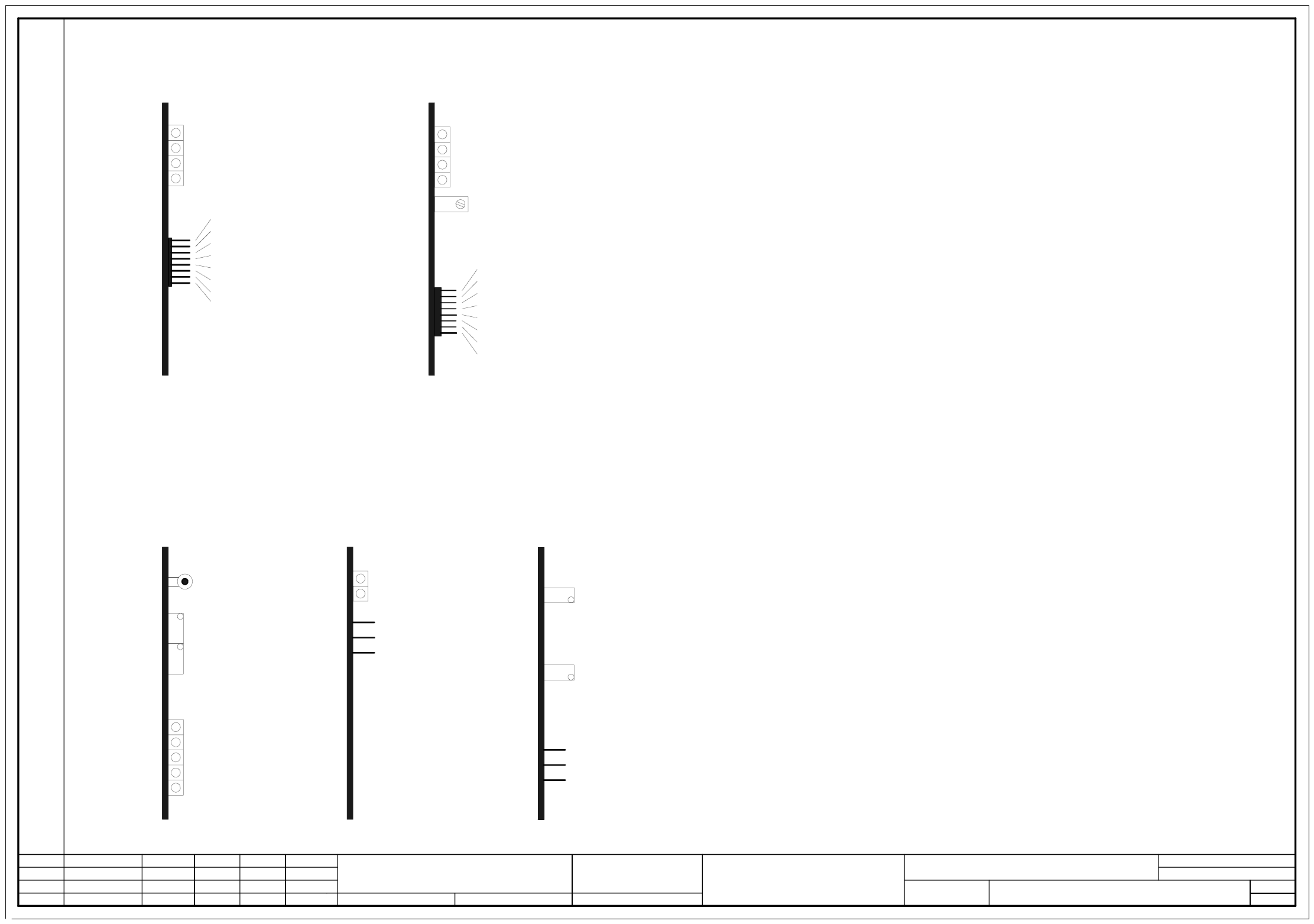
00354475-010201TD3 Servo unit, overview (sh. 2 of 2)
SIEMENS AGL&A EA
Status Modified Datum Name Stand. Orig. Repl. f. Repl. by
Document. status
Product status
Function status Date
Author
Check.
Sheet
Sh.
W
e
i
t
e
r
g
a
b
e
s
o
w
i
e
V
e
r
v
i
e
l
f
ä
l
t
i
g
u
n
g
d
i
e
s
e
r
U
n
t
e
r
l
a
g
e
,
V
e
r
-
w
e
r
t
u
n
g
u
n
d
M
i
t
t
e
i
l
u
n
g
i
h
r
e
s
I
n
h
a
l
t
s
n
i
c
h
t
g
e
s
t
a
t
t
e
t
,
s
o
w
e
i
t
n
i
c
h
t
a
u
s
d
r
ü
c
k
l
i
c
h
z
u
g
e
s
t
a
n
d
e
n
.
Z
u
w
i
d
e
r
h
a
n
d
l
u
n
g
e
n
v
e
r
-
p
f
l
i
c
h
t
e
n
z
u
S
c
h
a
d
e
n
e
r
s
a
t
z
.
A
l
l
e
R
e
c
h
t
e
v
o
r
b
e
h
a
l
t
e
n
,
i
n
s
b
e
s
o
n
d
e
r
e
f
ü
r
d
e
n
F
a
l
l
d
e
r
P
a
t
e
n
t
e
r
t
e
i
l
u
n
g
o
d
e
r
G
M
-
E
i
n
t
r
a
g
u
n
g
P
r
o
p
r
i
e
t
a
r
y
d
a
t
e
,
c
o
m
p
a
n
y
c
o
n
f
i
d
e
n
t
i
a
l
.
A
l
l
r
i
g
h
t
s
r
e
s
e
r
v
d
.
C
o
n
f
i
e
a
t
i
t
r
e
d
e
s
e
c
r
e
t
d
´
e
n
t
r
e
p
r
i
s
e
.
T
o
u
s
d
r
o
i
t
s
r
e
s
e
r
v
e
s
.
C
o
m
u
n
i
c
a
d
o
c
o
m
o
s
e
g
r
e
d
o
e
m
p
r
e
s
a
r
i
a
l
.
R
e
s
e
r
v
a
d
o
s
t
o
d
o
s
o
s
d
i
r
e
i
l
o
s
.
C
o
n
f
i
a
d
o
c
o
m
o
s
e
c
r
e
t
e
i
n
d
u
s
t
r
i
a
l
.
N
o
s
r
e
s
e
r
v
a
m
o
s
t
o
d
o
s
l
o
s
d
e
r
e
c
h
o
s
.
2.
1.
1.
25.05.2000
20.03.2002
25.05.2000
Tuth
Tuth
Tuth 04.05.2001
Tuth
00354475-010201TD3
SMD placement system Siplace S-27 HM
Servo unit, overview
2
2
Servoeinschub / Servo Unit S-27 HM (Cards )
MP2: Strom-Sollwert
MP3: Strom-Istwert
MP6: Ausgang Stromregler
MP1: Strom-Sollwert
MP4: Strom-Istwert
"I-Soll (U)"
Betriebsbereit / Ready
Endstufenfreigabe / Power stage enabled
Effektivstrombegrenzung / r.m.s. current limit
Störung / Error
Drehzahlsollwert
Sollwert Krafteingang
Tacho (echte Tachospannung)
Stromsollwert (Ausg. Drehzahlregler)
Stromistwert
Sensorstop-Signal
Verstärker Elektronik GND
Motorstellgröße (Ausg. Stromregler)
Ns
Ie
Is
Ta
IA
Ii
0V
Ss
T
B
S
T
D
S
X1
Gain
Zero point correction
X2
Y1
Y2
Distance
Reset
A
n
t
i
c
r
a
s
h
b
o
a
r
d
T
a
c
h
o
a
n
a
l
y
s
i
s
X gain
Y gain
GND
Nom. rotational speed value
Nom. force
Tacho (actual tacho voltage)
Nom current value (from speed controller)
Actual current value
Sensor stop signal
Amplifier reference GND
Motor controller signal
Ns
Ie
Is
Ta
IA
Ii
0V
Ss
MP5: Ausgang-
Stromregler
MP7: Frei
+15V
-15V
P
o
w
e
r
s
u
p
p
l
y
c
a
r
d
+
/
-
1
5
V
+15V
-15V
GND
Y gain
X gain
Betriebsbereit / Ready
Endstufenfreigabe / Power stage enabled
Effektivstrombegrenzung / r.m.s. current limit
Störung / Error
MP8: Bezugspotential "0V"
"I-Soll (W)"
"I-ist (U)"
"I-ist (W)"
"U-Soll (U)"
"U-Soll (W)"
MP1: Nom. current value U
MP2: Nom. current value W
MP3: Actual current value U
MP4: Actual Current Value W
MP5: Current regulator output U
MP6: Current regulator output W
MP7: Not used
MP8: 0V reference
Tacho
4 - 7
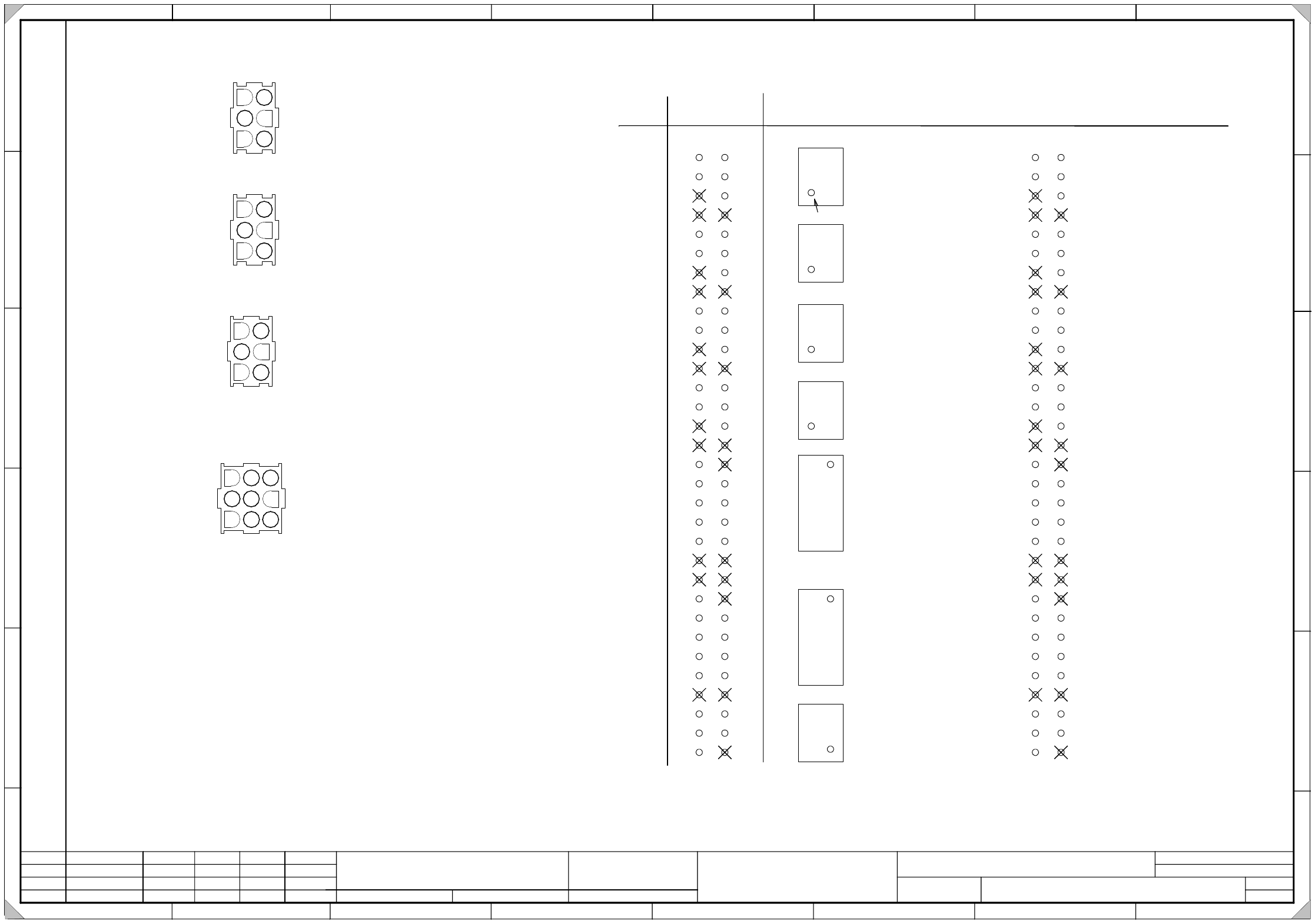
00354476-010201TD3 Servo unit, basic module, overview (connector assignment) (sh. 1 of 3)
SIEMENS AG
L&A EA
Status Modified Date Name Standard Orig. Repl.f. Repl. by
Document status
Product status
Function status Date
Author
Check.
Sheet
Sh.
W
e
i
t
e
r
g
a
b
e
s
o
w
i
e
V
e
r
v
i
e
l
f
ä
l
t
i
g
u
n
g
d
i
e
s
e
r
U
n
t
e
r
l
a
g
e
,
V
e
r
-
w
e
r
t
u
n
g
u
n
d
M
i
t
t
e
i
l
u
n
g
i
h
r
e
s
I
n
h
a
l
t
s
n
i
c
h
t
g
e
s
t
a
t
t
e
t
,
s
o
w
e
i
t
n
i
c
h
t
a
u
s
d
r
ü
c
k
l
i
c
h
z
u
g
e
s
t
a
n
d
e
n
.
Z
u
w
i
d
e
r
h
a
n
d
l
u
n
g
e
n
v
e
r
-
p
f
l
i
c
h
t
e
n
z
u
S
c
h
a
d
e
n
e
r
s
a
t
z
.
A
l
l
e
R
e
c
h
t
e
v
o
r
b
e
h
a
l
t
e
n
,
i
n
s
b
e
s
o
n
d
e
r
e
f
ü
r
d
e
n
F
a
l
l
d
e
r
P
a
t
e
n
t
e
r
t
e
i
l
u
n
g
o
d
e
r
G
M
-
E
i
n
t
r
a
g
u
n
g
P
r
o
p
r
i
e
t
a
r
y
d
a
t
e
,
c
o
m
p
a
n
y
c
o
n
f
i
d
e
n
t
i
a
l
.
A
l
l
r
i
g
h
t
s
r
e
s
e
r
v
d
.
C
o
n
f
i
e
a
t
i
t
r
e
d
e
s
e
c
r
e
t
d
´
e
n
t
r
e
p
r
i
s
e
.
T
o
u
s
d
r
o
i
t
s
r
e
s
e
r
v
e
s
.
C
o
m
u
n
i
c
a
d
o
c
o
m
o
s
e
g
r
e
d
o
e
m
p
r
e
s
a
r
i
a
l
.
R
e
s
e
r
v
a
d
o
s
t
o
d
o
s
o
s
d
i
r
e
i
l
o
s
.
C
o
n
f
i
a
d
o
c
o
m
o
s
e
c
r
e
t
e
i
n
d
u
s
t
r
i
a
l
.
N
o
s
r
e
s
e
r
v
a
m
o
s
t
o
d
o
s
l
o
s
d
e
r
e
c
h
o
s
.
SIPLACE S27 SMD Placement System
Servo unit, basic module, overview
A
B
C
D
E
F
1 2 3 4 5 6 7 8
1
2 3 4 5 6 7 8
A
B
C
D
E
F
2.
1.
1.
26.05.2000
17.07.2001
26.05.2000
Tuth
Tuth
Tuth 17.07.2001
Tuth
3
00354476-010201TD3
Pin b a
Connector
1
2
3
4
5
6
7
8
9
10
11
12
13
14
15
16
17
18
19
20
21
22
23
24
25
26
27
28
29
30
31
32
1
5
2
6
X11a
1
9
2
10
X11e
1
5
2
6
X11b
1
5
2
6
X11c
1
5
2
6
X11d
1
9
2
10
X11f
1
5
2
6
X11g
Tachometer -
Axis Enable
key
n.c.
Tachometer -
Axis Enable
key
n.c.
Tachometer -
Axis Enable
key
n.c.
Tachometer -
Achse Enable
key
n.c.
Anit-crash1 prox.sw .1 X-axis
Anti-crash prox.sw. 2 X-axis
Anti-crash prox.sw. 1 Y-axis
Anti-crash prox.sw. 2 Y-axis
Distance sensor
n.c.
n.c.
Anti-crash prox.sw. 1 X-axis
Anti-crash prox.sw. 2 X-axis
Anti-crash prox.sw. 1 Y-axis
Anti-crash prox.sw. 2 Y-axis
Distance sensor
n.c.
+15V
GND
-15V
Tachometer +
Axis Enable (+15V)
n.c.
n.c.
Tachometer +
Axis Enable (+15V)
n.c.
n.c.
Tachometer +
Axis Enable (+15V)
n.c.
n.c.
Tachometer +
Axis Enable (+15V)
n.c.
n.c.
key
n.c.
Sending "Crash" signal to input
GND
GND distance sensor
n.c.
n.c.
key
n.c.
Sending "Crash" signal to input
GND
GND distance sensor
n.c.
+24V
+5V
key
Please note:
All pins marked with an X have to be cut out.
X2
1L+
1L+
2L+
1L+
1L+
1L+
X3
+12V
1L-
1L-
7L+
6L+
2L+/5L+
X4
+24V
1L-
1L-
7L+
6L+
+5V
1
2
3
4
5
6
1
2
3
4
5
6
1
2
3
4
5
6
1
2
3
4
5
6
7
8
9
1 = 7L+
2 = GND
3 = +15V
4 = +5V
5 = GND
6 = +24V
7 = 2L+
8 = GND
9 = 6L+
X14
Connector designation
X2
Pin 1-3 male connector 0.5 -2.1mm²
Pin 4-6 female connector 0.5 -2.1mm²
X3 Pin 1-6 male connector 0.5 -2.1mm²
X4 Pin 1-6 female connector 0.5 -2.1mm²
X14 Pin 1-9 female connector 0.5 -2.1mm²
X11
Anti-crash board
Connector assignment
Connector X11 viewed from the back
Codierstift im Stecker
1