S27HM Circuit Diagrams.pdf - 第46页
SIPLACE S-27 HM Detailed C ircuit Diagrams Folder 05/2005 US Edit ion 2 - i 2 Detaile d Circui t Diagrams NH01-020 101LD3 EMER GENCY- STOP circu it with powe r su pply 0 033681 2-xx or 0035 6395-xx (Japan versi on) 2 - 1…
1 - 32
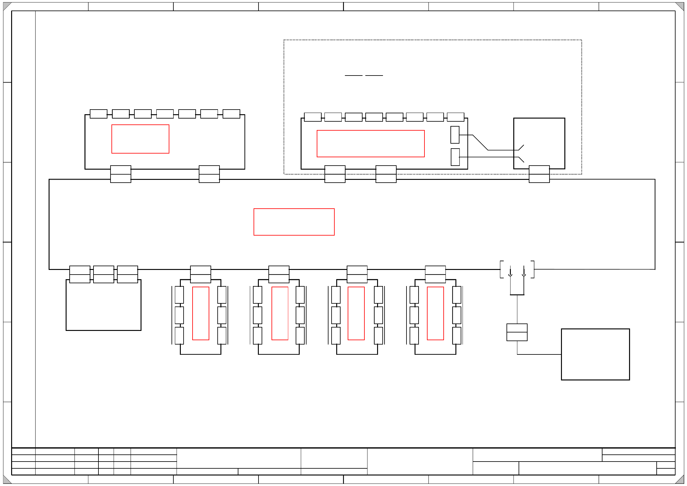
00364174-010101LD3 S-27 HM control unit (sh. 2 of 2)
DS01 26.06.01 Teknew
S27 HM control unit
SMD Placement System SIPLACE S27 HM
00364174-010101LD3
2
04.05.2001
Wollgarten
1 2345678
12345
67
8
F
E
D
C
B
A
F
E
D
C
B
A
P
r
o
p
r
i
e
t
a
r
y
d
a
t
e
,
c
o
m
p
a
n
y
c
o
n
f
i
d
e
n
t
i
a
l
.
A
l
l
r
i
g
h
t
s
r
e
s
e
r
v
d
.
C
o
n
f
i
e
a
t
i
t
r
e
d
e
s
e
c
r
e
t
d
'
e
n
t
r
e
p
r
i
s
e
.
T
o
u
s
d
r
o
i
t
s
r
e
s
e
r
v
e
s
.
C
o
m
u
n
i
c
a
d
o
c
o
m
o
s
e
g
r
e
d
o
e
m
p
r
e
s
a
r
i
a
l
.
R
e
s
e
r
v
a
d
o
s
t
o
d
o
s
o
s
d
i
r
e
i
l
o
s
.
C
o
n
f
i
a
d
o
c
o
m
o
s
e
c
r
e
t
e
i
n
d
u
s
t
r
i
a
l
.
N
o
s
r
e
s
e
r
v
a
m
o
s
t
o
d
o
s
l
o
s
d
e
r
e
c
h
o
s
.
W
e
i
t
e
r
g
a
b
e
s
o
w
i
e
V
e
r
v
i
e
l
f
ä
l
t
i
g
u
n
g
d
i
e
s
e
r
U
n
t
e
r
l
a
g
e
,
V
e
r
w
e
r
t
u
n
g
u
n
d
M
i
t
t
e
i
l
u
n
g
i
h
r
e
s
I
n
h
a
l
t
s
n
i
c
h
t
g
e
s
t
a
t
t
e
t
,
s
o
w
e
i
t
n
i
c
h
t
a
u
s
d
r
ü
c
k
l
i
c
h
z
u
g
e
s
t
a
n
d
e
n
.
Z
u
w
i
d
e
r
h
a
n
d
l
u
n
g
e
n
v
e
r
p
f
l
i
c
h
t
e
n
z
u
S
c
h
a
d
e
n
e
r
s
a
t
z
.
A
l
l
e
R
e
c
h
t
e
v
o
r
b
e
h
a
l
t
e
n
,
i
n
s
b
e
s
o
n
d
e
r
e
f
ü
r
d
e
n
F
a
l
l
d
e
r
P
a
t
e
n
t
-
e
r
t
e
i
l
u
n
g
o
d
e
r
G
M
-
E
i
n
t
r
a
g
u
n
g
.
L&A EA
Date
Author
Check.
Stand.Date NameModifiedStatus Orig. Repl. byRepl. f.
SIEMENS AG
Designer 7.1
Sheet
Sh.
X3ss
XK3su
X2ss
XK2su
X1ss
XK1su
X3sc
2
K
e
y
b
o
a
r
d
M
o
n
i
t
o
r
S
e
r
i
a
l
i
n
t
e
r
f
a
c
e
P
r
i
n
t
e
r
M
o
u
s
e
L
A
N
1
L
A
N
2
S
e
r
i
a
l
i
n
t
e
r
f
a
c
e
C
O
M
1
C
O
M
2
X1tc
Harddisk / Floppy
A17
(tc)
Data lines
Machine controller
A12 (sb)
XA1su XB2su XB3su
Multi-purpose backplane
A32 (su)
X4sbX3sb
X5sb X6sb X7sb
X10sb X11sb
X1sb X2sb
X12sb
X
9
s
b
X
8
s
b
Applies to GEM option only
X4sc X5sc X6sc X7sc X8sc X9sc
S
-
C
o
m
1
S
-
C
o
m
2
D
i
s
p
l
a
y
C
a
m
e
r
a
1
/
3
C
a
m
e
r
a
2
/
4
H
S
3
L
A
U
X
Vision system
A2
(sc)
X2scX1sc
XG8su XG9su
Power supply unit
A26
(ss)
Fan unit
A35 (ue)
X35ue
X35ue
r
d
b
u
Fan
P24 GND
X7sz
X
1
s
z
XC1su
X
2
s
z
X
3
s
z
X
4
s
z
X
5
s
z
X
6
s
z
A27
(sz)
A
x
e
s
t
r
a
c
k
s
X
N
o
m
i
n
a
l
v
a
l
u
e
s
S
t
a
r
X
Y
S
t
a
r
Y
A
x
e
s
t
r
a
c
k
s
X7ta
X
1
t
a
XC2su
X
2
t
a
X
3
t
a
X
4
t
a
X
5
t
a
X
6
t
a
A28
(ta)
A
x
i
s
r
e
a
r
p
a
n
e
l
Z
N
o
m
i
n
a
l
v
a
l
u
e
s
d
p
A
x
e
s
t
r
a
c
k
s
X7uc
X
1
u
c
XC3su
X
2
u
c
X
3
u
c
X
4
u
c
X
5
u
c
X
6
u
c
A29
(uc)
A
x
i
s
r
e
a
r
p
a
n
e
l
X
N
o
m
i
n
a
l
v
a
l
u
e
s
S
t
a
r
X
Y
S
t
e
r
n
Y
A
x
e
s
t
r
a
c
k
s
X7ud
X
1
u
d
XC4su
X
2
u
d
X
3
u
d
X
4
u
d
X
5
u
d
X
6
u
d
A30
(ud)
A
x
i
s
r
e
a
r
p
a
n
e
l
N
o
m
i
n
a
l
v
a
l
u
e
s
A
x
e
s
t
r
a
c
k
s
Z
d
p
Z
d
p
Z
d
p
The A27 A30 axes rear panels are part of the external cable harness !
See page 5-34
See page 5-18
See page 4-15
See page 1-30 See page 1-30 See page 1-30 See page 1-30

SIPLACE S-27 HM Detailed Circuit Diagrams Folder
05/2005 US Edition
2 - i
2 Detailed Circuit Diagrams
NH01-020101LD3 EMERGENCY-STOP circuit with power supply 00336812-xx
or 00356395-xx (Japan version) 2 - 1
NH01-020101LD3 EMERGENCY-STOP circuit - signaling circuit with power supply 00336812-xx
or 00356395-xx (Japan version) 2 - 2
NH02-010101LD3 EMERGENCY-STOP circuit with power supply 00375503-xx 2 - 3
NH02-010101LD3 EMERGENCY-STOP circuit - signaling circuit with power supply 00375503-xx 2 - 4
NH03-010101LD3 EMERGENCY-STOP circuit with power supply 00375539-xx (Japan version) 2 - 5
NH03-010101LD3 EMERGENCY-STOP circuit - signaling circuit with power supply 00375539-xx
(Japan version) 2 - 6
X01-010101LD3 X-axis, gantry 1 2 - 7
X02-010101LD3 X-axis, gantry 2 2 - 8
Y01-010101LD3 Y-axis, gantry 1 2 - 9
Y02-010101LD3 Y-axis, gantry 2 2 - 10
DR01-010101LD3 Collect&Place head - star axis, gantry 1 2 - 11
DR02-010101LD3 Collect&Place head - star axis, gantry 2 2 - 12
Z01-010101LD3 Collect&Place head - Z-axis, gantry 1 2 - 13
Z02-010101LD3 Collect&Place head - Z-axis, gantry 2 2 - 14
DP01-010101LD3 Collect&Place head - DP-axis, gantry 1 2 - 15
DP02-010101LD3 Collect&Place head - DP-axis, gantry 2 2 - 16
ZM01-010101LD3 Collect&Place head - adjustment drive motors - forced air valve,
CAN bus, gantry 1 2 - 17
ZM02-010101LD3 Collect&Place head - adjustment drive motors - forced air valve,
CAN bus, gantry 2 2 - 18
SV_STEU01-020101LD3 Power supply - control unit, terminal panel - conversion board, gantry 2 - 19
SV_SV01-020101LD3 Voltage supply for servo amplifier and anti-crash board with
power supply unit 00336812-xx/00356395-xx (sh. 1 of 3) 2 - 20
SV_SV01-020101LD3 Voltage supply for servo amplifier and anti-crash board with
power supply unit 00375503-xx/00375539-xx (sh. 2 of 3) 2 - 21
SV_SV01-020101LD3 Voltage supply for servo amplifier and anti-crash board (sh. 3 of 3) 2 - 22
LPT01-020101LD3 PCB single conveyor / PCB dual conveyor,
conveyor control TSP-201 (sh. 1 of 11) 2 - 23
LPT02-020101LD3 PCB single conveyor / PCB dual conveyor,
conveyor control TSP-201 (sh. 2 of 11) 2 - 24
LPT03-020101LD3 PCB single conveyor / PCB dual conveyor,
conversion board "conveyor"(sh. 3 of 11) 2 - 25
LPT04-020101LD3 PCB single conveyor / PCB dual conveyor,
conversion board "conveyor"(sh. 4 of 11) 2 - 26
LPT05-020101LD3 PCB single conveyor / PCB dual conveyor,
conversion board "conveyor"(sh. 5 of 11) 2 - 27
LPT06-020101LD3 PCB single conveyor / PCB dual conveyor,
conversion board "conveyor"(sh. 6 of 11) 2 - 28
LPT07-020101LD3 PCB single conveyor / PCB dual conveyor,
conversion board "transportation cheek A" (sh. 7 of 11) 2 - 29
LPT08-020101LD3 PCB single conveyor / PCB dual conveyor,
conversion board "transportation cheek B" (sh. 8 of 11) 2 - 30
LPT09-020101LD3 PCB single conveyor / PCB dual conveyor,

2 - ii
SIPLACE S-27 HM Detailed Circuit Diagrams Folder
05/2005 US Edition
conversion board "transportation cheek C" (sh. 9 of 11) 2 - 31
LPT10-020101LD3 PCB single conveyor / PCB dual conveyor,
conversion board "transportation cheek D" (sh. 10 of 11) 2 - 32
LPT11-020101LD3 PCB single conveyor / PCB dual conveyor,
conversion board "lifting table", track 1 + track 2 (sh. 11 of 11) 2 - 33
BT01-010101LD3 Component table, mobile, righthand side 2 - 34
BT01-010101LD3 Component table, mobile, lefthand side 2 - 35
GS01-010201LD3 Tape cutter, pneumatically operated, righthand side 2 - 36
GS02-010201LD3 Tape cutter, pneumatically operated, lefthand side 2 - 37
PW01-010101LD3 Nozzle changer 2 - 38
MTC01-010201LD3 MTC interface, righthand side 2 - 39
MTC02-010201LD3 MTC interface, lefthand side 2 - 40