S27HM Circuit Diagrams.pdf - 第87页
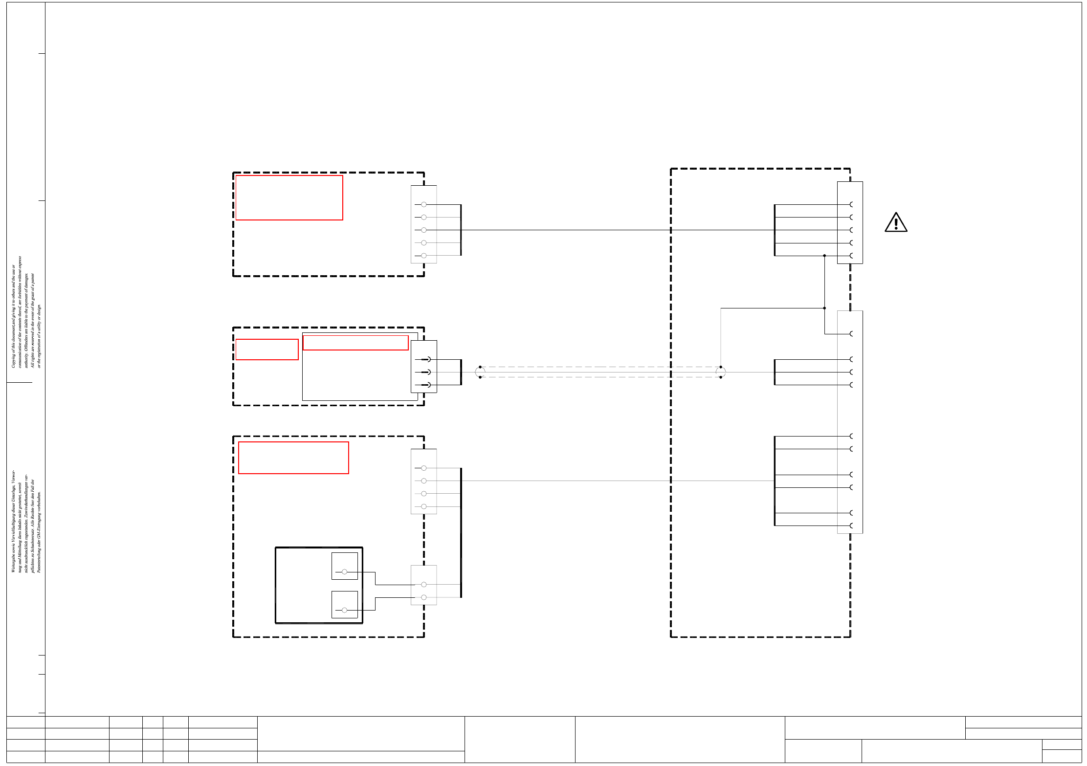
2 - 40 MTC02-0 10201 LD3 MTC in terface , lefthand side Doc. status Product status Function status SIE MEN S L&A E A bl bk bn bk bk bn bk bl (1) (2) (3) (4) 00375221-xx 4 3 2 1 2c X57a 1c 2a 3a 4a 1a 6c 5c 4c 3c wh b…
2 - 39
MTC01-010201LD3 MTC interface, righthand side
bn
Control unit
00364174-xx A13 (sd)
Communications assembly
Terminal board, I/O distributor
00353088-xx
2
X3ka
+
blbk
blbk
+24V
SLIO
MTC-interface, right-hand side
00322105-xx
Status DateModified Name Stand. Orig./Repl.f/Replaced by
Check.
Date
Author
Mat. no.:
CAD file:
30.05.05 Hi2.
1. 02.11.02 Hi
Hi02.11.021.
MTC01-010201LD3
GND
RxD
TxD
00326142-xx
SCOM 1
X1ka
(ka)
gnye
(Cable)
00321110-xx
Terminal board, voltages
00356643-xx
N
L3
L2
X206
L1
PE
(4)
(3)
(2)
(1)
gnye
MTC01.DWG
Stromlaufplan/Circuit diagram
Hi
30.05.2005
Sh.
Sh.
SMD Placement System SIPLACE S-27 HM
1
1
MTC interface, right-hand side
X56b
PE
4
3
2
1
2c
X57b
1c
2a
3a
4a
1a
6c
5c
4c
3c
wh
bn
gn
ye
gy
pk
wh
gn
bn
Spare
RxD
TxD
EMERGENCY-STOP, external, GND
EMERGENCY-STOP, external
EMERGENCY-STOP loop, to MTC
EMERGENCY-STOP loop, from MTC
Signalling circuit
EMERGENCY-STOP loop
PE
N
L3
L2
L1
wh
00322108-xx
(Cable)
00322112-xx
(Cable)
2
pk
wh
X210
1
20
1
gy
bn
X211
3
5
X2sd
2
6
7
ye
gn
wh
gn
Do not connect MTC!
Doc. status
Product status
Function status
SIEMENS
L&A EA
00375221-xx
bl
bk
bk
bn bn
bk
bk
bl
(1)
(2)
(3)
(4)
See page 5-10
See page 4-15
See page 3-6
See page 3-17
See page 3-19
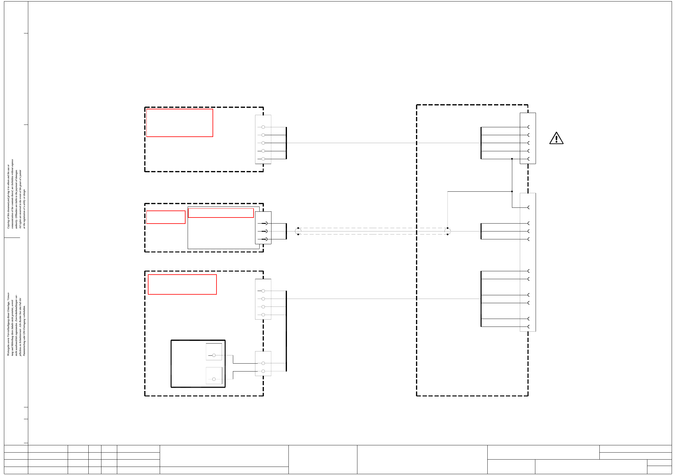
2 - 40
MTC02-010201LD3 MTC interface, lefthand side
Doc. status
Product status
Function status
SIEMENS
L&A EA
bl
bk
bn
bk bk
bn
bk
bl
(1)
(2)
(3)
(4)
00375221-xx
4
3
2
1
2c
X57a
1c
2a
3a
4a
1a
6c
5c
4c
3c
wh
bn
gn
ye
gy
pk
wh
gn
bn
Spare
RxD
TxD
EMERGENCY-STOP, external, GND
EMERGENCY-STOP, external
EMERGENCY-STOP loop, to MTC
EMERGENCY-STOP loop, from MTC
Signalling circuit
EMERGENCY-STOP loop
PE
N
L3
L2
L1
wh
00322107-xx
(Cable)
00322111-xx
(Cable)
2
pk
wh
X210
1
20
1
gy
bn
X211
3
5
X4sd
2
4
5
ye
gn
wh
gn
bn
Control unit
00364174-xx A13 (sd)
Communications assembly
Terminal board, I/O distributor
00353088-xx
blbk
blbk
MTC interface, left-hand side
00322104-xx
Status DateModified Name Stand. Orig./Repl.f/Replaced by
Check.
Date
Author
Mat. no.:
CAD file:
1.
2.
1. 02.11.02
30.05.05
02.11.02 Hi
Hi
Hi
30.05.2005
Hi
MTC02-010201LD3
(ka)
SLIO
2
X1ka
+24V
+
X3ka
GND
RxD
TxD
SCOM 3
00326142-xx
00322109-xx
(Cable)
gnye
Terminal board, voltages
00356643-xx
PE
N
L3
L2
gnye
(4)
(3)
(2)
X206
L1
(1)
Do not connect MTC!
MTC02.DWG
Stromlaufplan/Circuit diagram
Sh.
Sh.
SMD Placement System SIPLACE S-27 HM
1
1
MTC interface, left-hand side
X56a
PE
See page 5-10
See page 4-15
See page 3-6
See page 3-17
See page 3-19

SIPLACE S-27 HM Detailed Circuit Diagrams Folder
05/2005 US Edition
3 - i
3 Circuit diagrams
00300272-070101LD3 Line filter with discharge reactor 3 - 1
00336812-040301LD3 Power supply, circuit diagram approx. up to serial no. 259 (sh. 1 of 2) 3 - 2
00336812-040301LD3 Power supply, circuit diagram approx. up to serial no. 259 (sh. 2 of 2) 3 - 3
00337065-060101LD3 X motor, S-27 HM 3 - 4
00337066-030101LD3 Y motor, S-27 HM 3 - 5
00353088-010601LD3 Terminal block, I/O distributor (sh. 1 of 3) 3 - 6
00353088-010601LD3 Terminal block, I/O distributor (sh. 2 of 3) 3 - 7
00353088-010601LD3 Terminal block, I/O distributor (sh. 3 of 3) 3 - 8
00354476-010301LD3 Servo unit, S-27 HM, basic module, wiring (sh. 1 of 5) 3 - 9
00354476-010301LD3 Servo unit, S-27 HM, basic module, wiring (sh. 2 of 5) 3 - 10
00354476-010301LD3 Servo unit, S-27 HM, basic module, wiring (sh. 3 of 5) 3 - 11
00354476-010301LD3 Servo unit, S-27 HM, basic module, wiring (sh. 4 of 5) 3 - 12
00354476-010301LD3 Servo unit, S-27 HM, basic module, wiring (sh. 5 of 5) 3 - 13
00356395-040201LD3 Power supply, circuit diagram, option for Japan
approx. up to serial no. 259 (sh. 1 of 2) 3 - 14
00356395-040201LD3 Power supply, circuit diagram, option for Japan
approx. up to serial no. 259 (sh. 2 of 2) 3 - 15
00356643-010301LD3 Circuit diagram, terminal panel voltages
approx. up to serial no. 224 (sh. 1 of 2) 3 - 16
00356643-010301LD3 Circuit diagram, terminal panel voltages
approx. up to serial no. 224 (sh. 2 of 2) 3 - 17
00375221-010102LD3 Circuit diagram, terminal block voltages
approx. from serial no. 225 (sh. 1 of 2) 3 - 18
00375221-010102LD3 Circuit diagram, terminal block voltages
approx. from serial no. 225 (sh. 2 of 2) 3 - 19
00375503-020101LD3 Power supply unit, circuit diagram
approx. from serial no. 260 (sh. 1 of 2) 3 - 20
00375503-020101LD3 Power supply unit, circuit diagram
approx. from serial no. 260 (sh. 2 of 2) 3 - 21
00375539-010101LD3 Power supply unit, circuit diagram, Japan version
approx. from serial no. 260 (sh. 1 of 2) 3 - 22
00375539-010101LD3 Power supply unit, circuit diagram, Japan version
approx. from serial no. 260 (sh. 2 of 2) 3 - 23