00197623-03_VD_708.1_SP2_DE_EN.pdf - 第15页
Station Software 7 08.1 SP2 / Version Description Ausgabe 10/2015 E dition 15 5.9 Additional Repick C ompatible mode : C omplet e To prevent a machine stop, this opt ion allows an additional repi ck although the v alue f…
Station Software 708.1 SP2 / Version Description Ausgabe 10/2015 Edition
14
NOTICE
Selection of the component shapes in SIPLACE Pro
In SIPLACE Pro the 0201 component shapes (= inch-based) or 03015m
(= metric-based) can be selected for the placement process.
SIPLACE Pro treats the metric-based 0201 component shapes as 03015m component
shapes. Therefore, in this case 03015m has to be selected and not 0201!
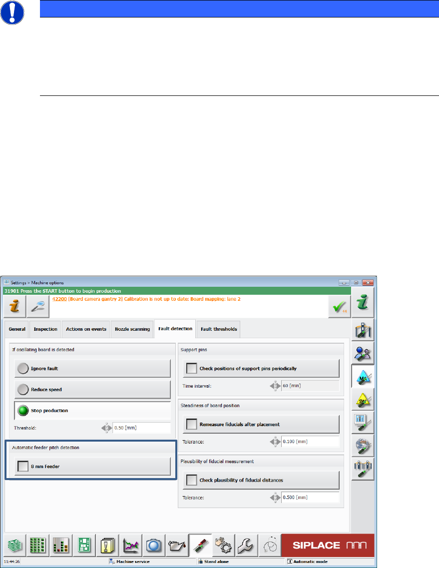
5.8 Optional Automatic Detection of the Feeder Pitch
Compatible mode: Complete
Components in tapes for 8 mm and 2x8 mm X-feeders are often delivered with different feeder
pitches dependent on the manufacturer. Thus, it is not possible to work with a fixed setting what in
the worst case might cause a big loss of components from a tape reel.
For this, the already available Automatic feeder pitch detection function has been enhanced. As
of this station software version, an optional automatic detection of the feeder pitch can be set and
performed during runtime.
The check can be enabled or disabled in the Machine options on the GUI.
Figure 5-6: Automatic detection of the feeder pitch
Station Software 708.1 SP2 / Version Description Ausgabe 10/2015 Edition
15
5.9 Additional Repick
Compatible mode: Complete
To prevent a machine stop, this option allows an additional repick although the value for repicks is
set to 1 in SIPLACE Pro.
An additional repick will be performed in the following cases, provided that 500 successful repicks
have been performed before (valid for each case):
– after SIPLACE Vision has recognized a material defect
– after an empty tape pocket was recognized
The option is set in the SetupCtrl.xml configuration file.
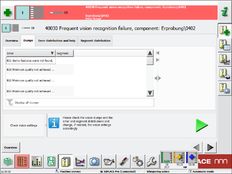
5.10 Handling of Frequent Vision Errors
Compatible mode: Complete
The display of detailed messages for frequent Vision errors has been enhanced.
In the Overview tab the same information on component and error rate is displayed as before.
In the Dumps tab the dump files are displayed. Beneath the list it can also be filtered by error
numbers and their frequency.
Figure 5-7: Frequent Vision errors – Dumps tab
Station Software 708.1 SP2 / Version Description Ausgabe 10/2015 Edition
16
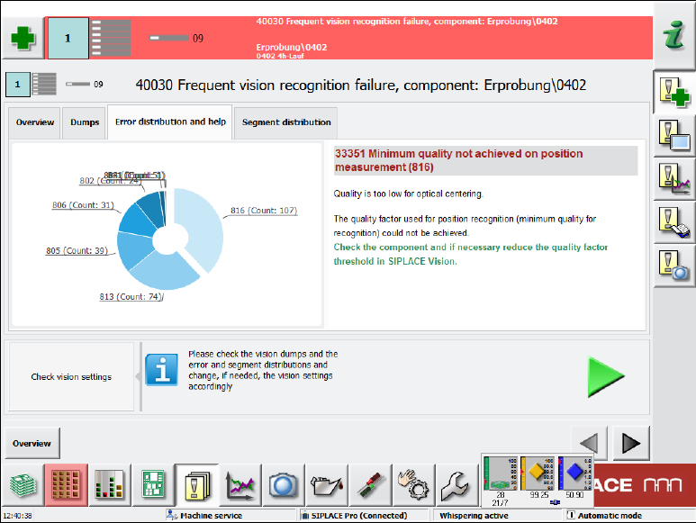
In the Error distribution and help tab a diagram displays all errors. If an error is selected by
clicking on it, corresponding help assistance is displayed to the right.
Figure 5-8: Frequent Vision errors – Error distribution and help tab
In the Segment distribution tab the same diagram is displayed but additionally with the counter
for the respective segment.
5.11 Enhanced Placement Error Analysis
Compatible mode: Complete
In the Board view, an inspection option can be selected for each placement position. A Vision
image can be taken of the components before pickup and after placement on the board and the
dump files can be stored. However, with these analysis options it is not possible to differentiate if
the placement problem occured on the way to the placement position, during placement or after
placement. For this, an inspection of the component position is required for one or several
placement positions immediately before the placement process takes place (before the z-axis is
started for placement).
The diagnosis functionality in the Board view has been enhanced by the Compare Image before
placement option.