00193161-01.pdf - 第50页
Placement of 0 402 components Manual S-20/S-23 HM/S-25 HM/F4/F5 HM/HS-50 03/2001 edition 50 5.3 Using a t ape support (spacer) with p aper t apes 5.3.1 S pacer type s If 0402 compo nents are fed in paper tapes, a tape sp…
Manual S-20/S-23 HM/S-25 HM/F4/F5 HM/HS-50 Placement of 0402 components
03/2001 edition
49
5.2.3 Setting the step size to a pitch of 2 mm (3 x 8 mm SII feeder)
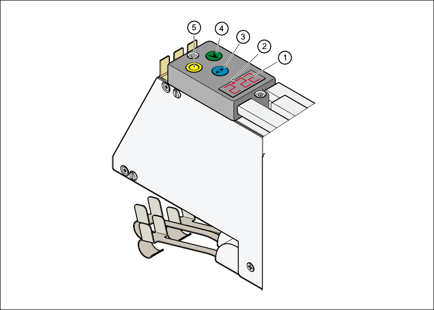
Fig. 5 - 5 Setting the step size to a pitch of 2mm (3 x 8 mm SII feeder)
a 6WHSVL]HGLVSOD\
s 5HGGRWLQGLFDWHVWKHVHOHFWHGWUDFN
d 6HOHFWEXWWRQEOXH
f ,QGH[EXWWRQJUHHQ
g )RLOEXWWRQ\HOORZ
Å Use the blue Select button d to select the track. A red dot s indicates the selected track.
Å Hold down the green Index button f until the display a for the selected track starts to flash.
Å Keep holding down the green Index button f and press the yellow Foil button g. The step
size on the feeder is changed over and displayed. Set the step size to 2mm.
Å Release the green Index button. The flashing stops and the display remains on to indicate that
the step size of 2 mm has been set on the feeder.

Placement of 0402 components Manual S-20/S-23 HM/S-25 HM/F4/F5 HM/HS-50
03/2001 edition
50
5.3 Using a tape support (spacer) with paper tapes
5.3.1 Spacer types
If 0402 components are fed in paper tapes, a tape spacer must be used at the pick-up position in
the feeder.
0402 spacer
for 8 mm SII feeders
Article number 00330832-01
(2 spacers are required for each feeder)
0402 spacer
for 3 x 8 mm S feeders
Article number 00349418-01
(3 spacers are required for each feeder)
Centering lugs for latching the spacer into position
in the pick-up or park position (see point ) in Fig.
5 - 2
, on page 46).
Feeders Article number Tape support Material
2 x 8 mm SII 00141096-xx 00330832-01 Aluminum
3 x 8 mm S 00141098-xx 00349418-01 Plastic
3 x 8 mm S for 0201/0402
components
00141099-xx No spacer required
A
P
Manual S-20/S-23 HM/S-25 HM/F4/F5 HM/HS-50 Placement of 0402 components
03/2001 edition
51
5.3.2 Positioning the 0402 tape spacer (2 x 8 mm SII feeder)
The position of the tape spacer depends on which version of the hold-down device is used. There
are one-sided or two-sided hold-down devices.
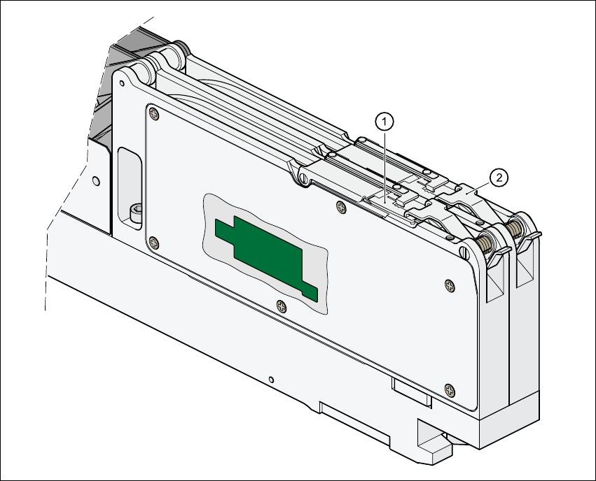
Fig. 5 - 6 Replacing the component cover, removing the foil removal beak
a &RPSRQHQWFRYHU
s 7ZRVLGHGKROGGRZQGHYLFH