00193161-01.pdf - 第62页
Placement of 0 402 components Manual S-20/S-23 HM/S-25 HM/F4/F5 HM/HS-50 03/2001 edition 62 Fig. 8 - 2 Selecting and loading the p ackage form Å Clic k on th e ‘ T es t Componen t ’ icon. The ‘ T e st Component ’ menu op…
Manual S-20/S-23 HM/S-25 HM/F4/F5 HM/HS-50 Placement of 0402 components
03/2001 edition
61
8 Checking the vision settings on the station
PLEASE NOTE
The vision functions can only be called at ‘line engineer’ access level or higher.
In this manual, the vision settings are explained with reference to the HS-50 placement machine.
However, they also apply to the S-20, S-23/25 HM, F4 and F5 HM since the order of the menus
is the same. 8
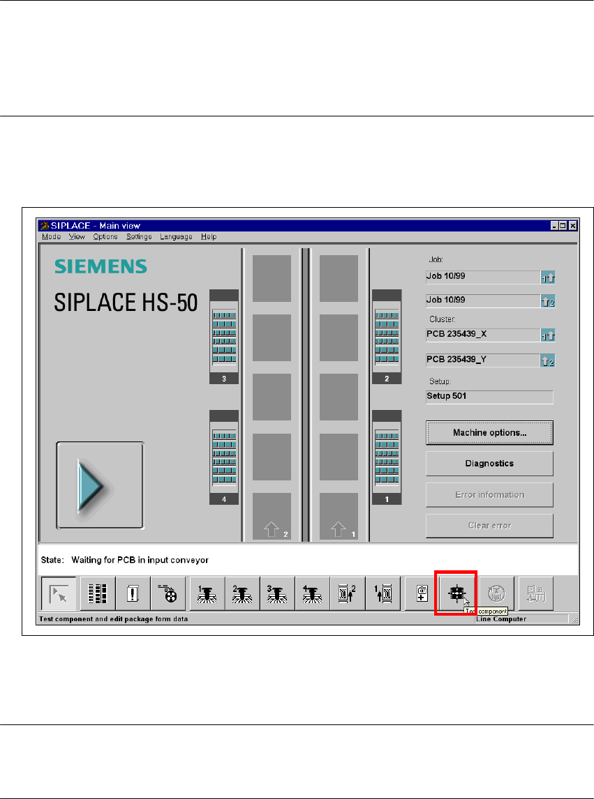
8.1 Selecting the ‘Test Component’ menu
Å
Select the ‘Test Component’ icon from the main view.
8
Fig. 8 - 1 From the HS-50 user interface, select the ‘Test component’ menu
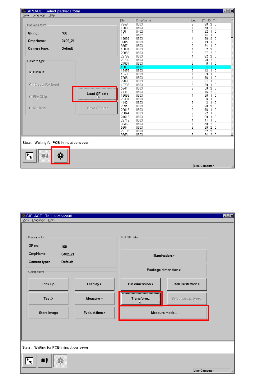
Å From the ‘Package Form Selection’ menu, highlight package form 100 with the cyan bar.
Å Click on the ‘Load GF’ button to load the package form.
PLEASE NOTE:
GF number 100 is assigned to 0402 resistors.
GF number 101 is assigned to 0402 capacitors. 8
Placement of 0402 components Manual S-20/S-23 HM/S-25 HM/F4/F5 HM/HS-50
03/2001 edition
62
Fig. 8 - 2 Selecting and loading the package form
Å Click on the ‘Test Component’ icon. The ‘Test Component’ menu opens.
8
Fig. 8 - 3 ‘Test Component’ menu
Manual S-20/S-23 HM/S-25 HM/F4/F5 HM/HS-50 Placement of 0402 components
03/2001 edition
63
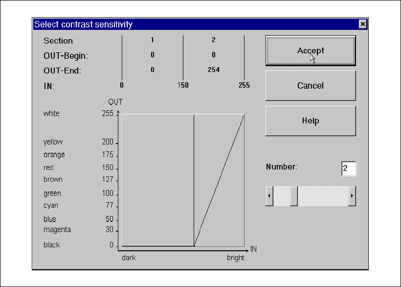
8.2 Checking the contrast sensitivity
Å Click on the ‘Table …’ button.
The ‘Contrast Sensitivity’ selection box appears.
Fig. 8 - 4 ‘Contrast Sensitivity’ selection box
The contrast sensitivity values and curve should correspond to those shown in the diagram
above. If this is not the case, modify the values. 8