00193161-01.pdf - 第66页
Placement of 0 402 components Manual S-20/S-23 HM/S-25 HM/F4/F5 HM/HS-50 03/2001 edition 66 Å Clic k on th e ‘ Integra tion Setti ngs ’ butt on. The fo llowing opti ons must be check ed in the ‘ Size Meas uring Mo de, I …
Manual S-20/S-23 HM/S-25 HM/F4/F5 HM/HS-50 Placement of 0402 components
03/2001 edition
65
8.3.1 Parameters for ‘SIZE’ measuring mode
PLEASE NOTE:
Only the ‘Size’ and ‘Lead’ check boxes must be checked in the Measuring Mode menu. The ‘Row’,
‘Corner’, ‘Grid’ and ‘Ball’ measuring modes must NOT be checked. 8
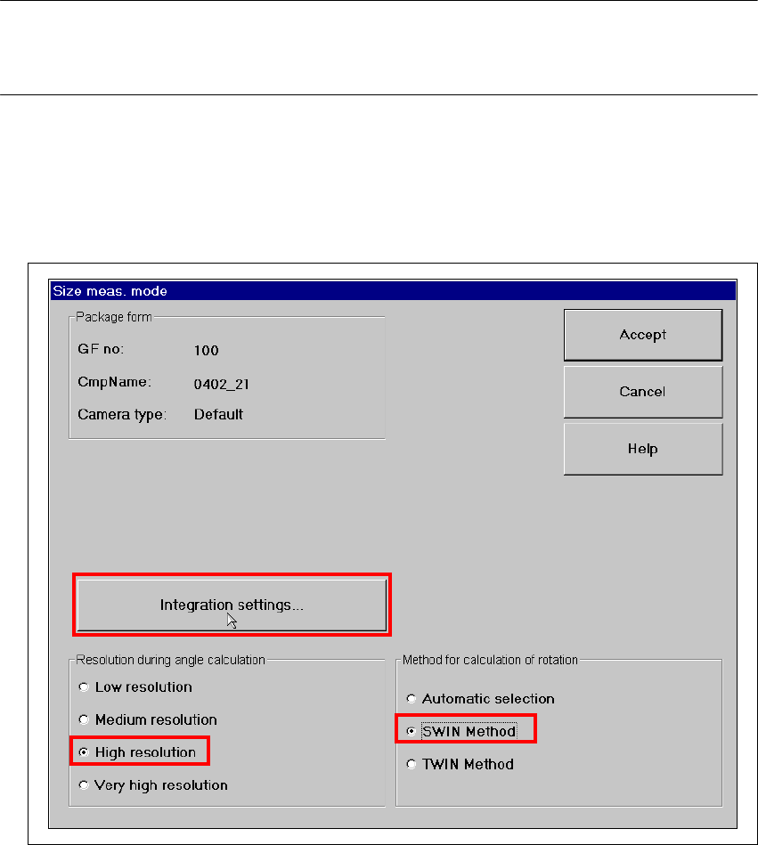
Å Click on the ‘Set…’ button. The 'Size measuring mode' window opens.
Settings:
Resolution for angle calculation high resolution
Method for calculation of rotation SWIN method 8
Fig. 8 - 6 Setting ‘Size’ measuring mode
Placement of 0402 components Manual S-20/S-23 HM/S-25 HM/F4/F5 HM/HS-50
03/2001 edition
66
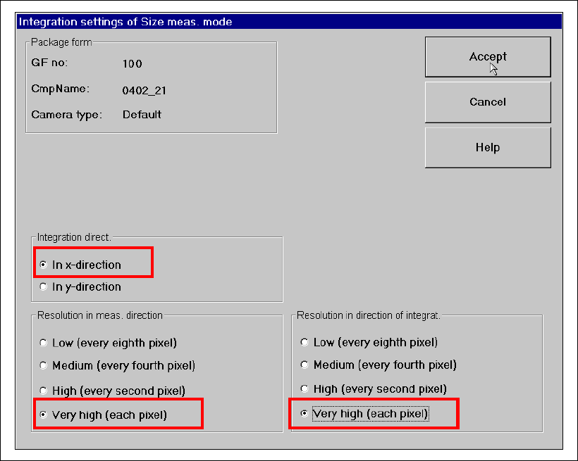
Å Click on the ‘Integration Settings’ button. The following options must be checked in the ‘Size
Measuring Mode, Integration Settings’ window:
– Integration direction in the X direction
– Resolution in meas. direction very high (every pixel)
– Resolution in direction of integration very high (every pixel)
Fig. 8 - 7 ‘Size’ measuring mode: Integration settings

Manual S-20/S-23 HM/S-25 HM/F4/F5 HM/HS-50 Placement of 0402 components
03/2001 edition
67
8.3.2 Parameters for ‘LEAD’ measuring mode
Å From the ‘Measuring Mode’ menu (see Fig. 8 - 5 on page 64), click on the ‘Set …’ button for
‘Lead’. The following options must be checked in the ‘Lead Measuring Mode’ window:
– Measur: Tip measurement via outer tips
– Window: Separately for each pin
Fig. 8 - 8 Setting ‘Lead’ measuring mode