00193161-01.pdf - 第53页
Manual S-20/S-23 HM/S-25 HM/F4/F5 HM /HS-50 Placement of 0402 components 03/2001 edition 53 5.3.4 Positioni ng the 0402 sp acer on th e one-sided hold- down device Fig. 5 - 8 Positioning the 0402 spacer on the one-sided …
Placement of 0402 components Manual S-20/S-23 HM/S-25 HM/F4/F5 HM/HS-50
03/2001 edition
52
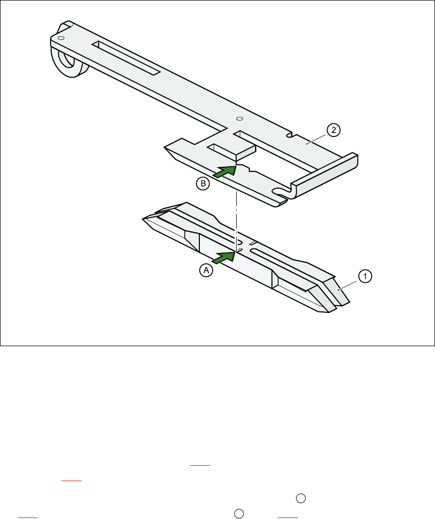
5.3.3 Positioning the 0402 spacer on the two-sided hold-down device
Fig. 5 - 7 Positioning the 0402 spacer on the two-sided hold-down device
a VSDFHU
s &RPSRQHQWFRYHU
– Insert the 0402 spacer (item a in Fig. 5 - 7
) so that it is level with the component cover (item
s in Fig. 5 - 7
) in the tape channel of the feeder module.
– Position the 0402 spacer so that the notch in the center (item in Fig.
5 - 7
) is flush with the saw-toothed recess (item in Fig. 5 - 7) in the component cover.
A
B
Manual S-20/S-23 HM/S-25 HM/F4/F5 HM/HS-50 Placement of 0402 components
03/2001 edition
53
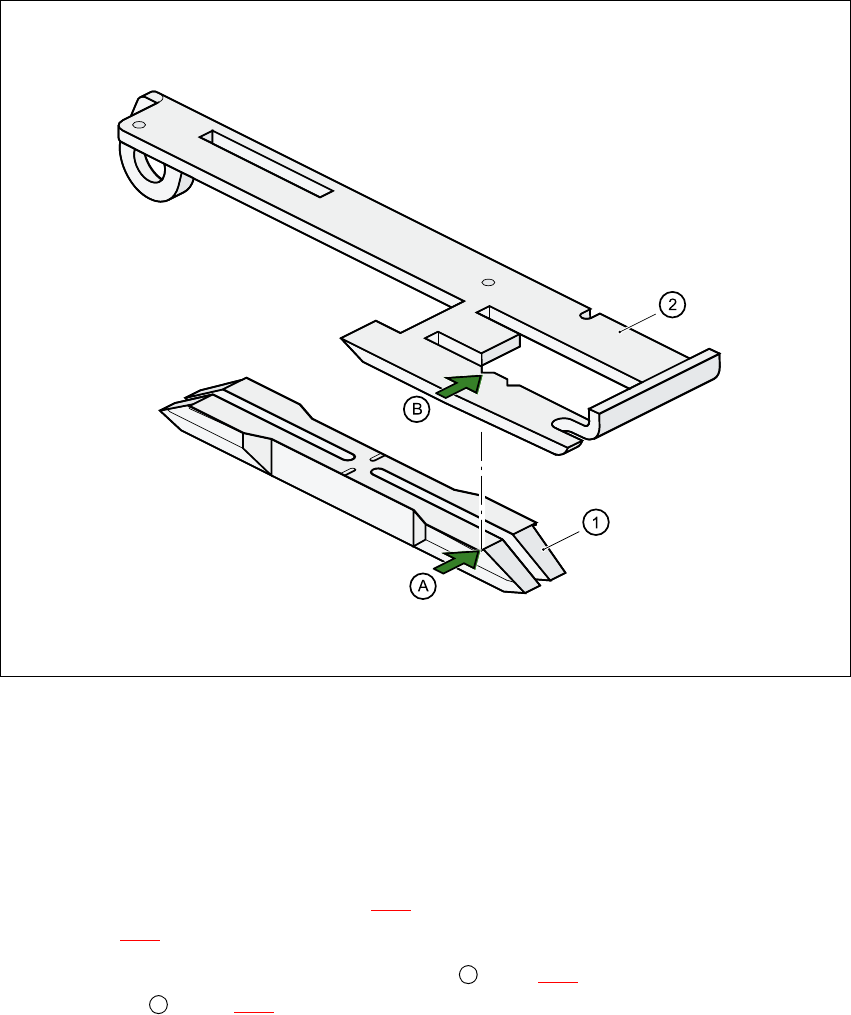
5.3.4 Positioning the 0402 spacer on the one-sided hold-down device
Fig. 5 - 8 Positioning the 0402 spacer on the one-sided hold-down device
a VSDFHU
s &RPSRQHQWFRYHU
– Insert the 0402 spacer (item a in Fig. 5 - 8
) so that it is level with the component cover (item
s in Fig. 5 - 8
) in the tape channel of the feeder module.
– Position the 0402 spacer so that the edge (item in Fig 5 - 8
) is flush with the saw-toothed
recess (item in Fig. 5 - 8
) in the component cover.
A
B
Placement of 0402 components Manual S-20/S-23 HM/S-25 HM/F4/F5 HM/HS-50
03/2001 edition
54
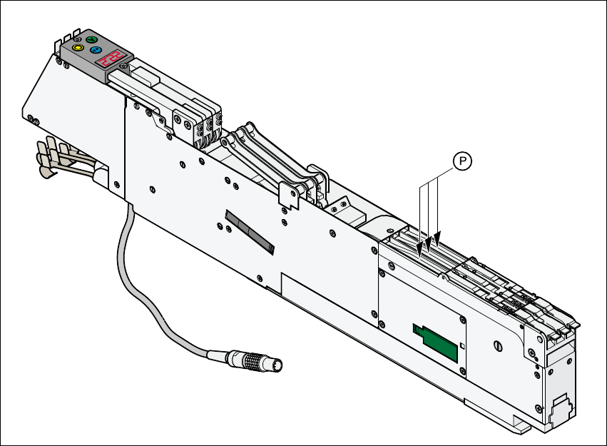
5.3.5 Positioning the 0402 tape spacer on the 3 x 8 mm S feeder
This feeder has holes at the pick-up position for centering the 0402 tape spacer. The notches in
the center of the tape spacer are aligned with the pick-up position. When the tape spacer is no
longer required, it can be inserted at the feeder park position.
Fig. 5 - 9 Park position for the 0402 tape spacer on the 3 x 8mm S feeder