00193161-01.pdf - 第58页
Placement of 0 402 components Manual S-20/S-23 HM/S-25 HM/F4/F5 HM/HS-50 03/2001 edition 58 7.3 Cleaning cer amic nozzles Å Regula rly cl ean the ce ramic n ozzles to avoid pick- up and cen terin g errors . Å When c lean…
Manual S-20/S-23 HM/S-25 HM/F4/F5 HM/HS-50 Placement of 0402 components
03/2001 edition
57
7 Nozzles
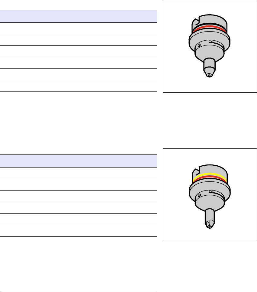
7.1 Nozzle type 725/925
This nozzle is specially designed for 0402 components. Its small suction surface makes it
insensitive to dirt
*)
and therefore ideal for placing 0402 components.
7.2 Nozzle type 701/901
This nozzle is suitable for placing the 0402 and 0603
component ranges. The larger suction surface makes it
more susceptible to dirt
*)
, however. If it is used for placing
0402 components, the ‘Nozzle scanning’ function must be
activated.
Nozzle type 725/925
Suction cross-section [mm²]0.16
Height [mm] 16
Material Ceramic/Vectra
Placeable components 0402
Color coding RED/BLACK
Article number 00333652-xx
Nozzle type 701/901
Suction cross-section [mm²]0.20
Height [mm] 16
Material Ceramic/Vectra
Placeable components 0402 / 0603
Color coding RED/YELLOW
Article number 00322603-xx
*) The susceptibility to dirt and thus the nozzle cleaning intervals
depend on the quality of the solder paste application.
Placement of 0402 components Manual S-20/S-23 HM/S-25 HM/F4/F5 HM/HS-50
03/2001 edition
58
7.3 Cleaning ceramic nozzles
Å Regularly clean the ceramic nozzles to avoid pick-up and centering errors.
Å When cleaning the nozzles, follow the ‘Cleaning instructions for ceramic nozzles’ job guide.
Manual S-20/S-23 HM/S-25 HM/F4/F5 HM/HS-50 Placement of 0402 components
03/2001 edition
59
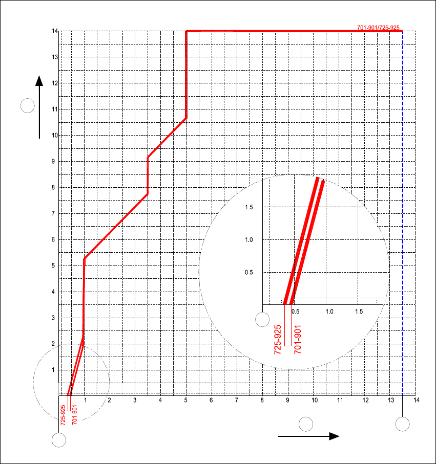
7.4 Nozzle contour diagrams
7.4.1 Nozzle contour for 701/901 and 725/925 nozzle types, narrow side
Fig. 7 - 1 Nozzle contour for 701/901 and 725/925 nozzle types, narrow side, ceramic/Vectra
a 'LIIHUHQFHLQKHLJKWEHWZHHQFRPSRQHQWV>PP@
s 3ODFHPHQWVKDGRZ>PP@
d 2XWHUHGJHRIFRGLQJGLVF
f 1R]]OHFHQWHU
1
2
3
4
4