00193161-01.pdf - 第65页
Manual S-20/S-23 HM/S-25 HM/F4/F5 HM /HS-50 Placement of 0402 components 03/2001 edition 65 8.3.1 Parameters for ‘ SIZE ’ measuring mode PLEA SE NOT E: Only the ‘ Size ’ and ‘ Lead ’ check box es must be chec ked in the …
Placement of 0402 components Manual S-20/S-23 HM/S-25 HM/F4/F5 HM/HS-50
03/2001 edition
64
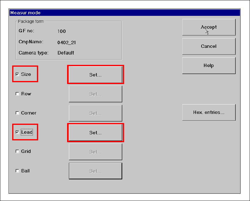
8.3 Checking the ‘SIZE’ and ‘LEAD’ measuring mode parameters
Å From the ‘Test Component’ menu, click on the ‘Measuring Mode’ icon. The ‘Measuring Mode’
menu appears. The ‘Size’ and ‘Lead’ check boxes must be checked. All the others should be
left unchecked.
Fig. 8 - 5 ‘Measuring Mode’ menu
Manual S-20/S-23 HM/S-25 HM/F4/F5 HM/HS-50 Placement of 0402 components
03/2001 edition
65
8.3.1 Parameters for ‘SIZE’ measuring mode
PLEASE NOTE:
Only the ‘Size’ and ‘Lead’ check boxes must be checked in the Measuring Mode menu. The ‘Row’,
‘Corner’, ‘Grid’ and ‘Ball’ measuring modes must NOT be checked. 8
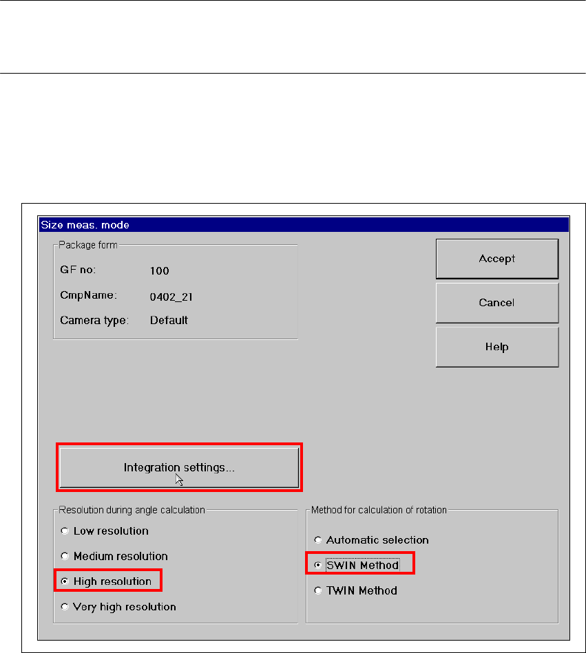
Å Click on the ‘Set…’ button. The 'Size measuring mode' window opens.
Settings:
Resolution for angle calculation high resolution
Method for calculation of rotation SWIN method 8
Fig. 8 - 6 Setting ‘Size’ measuring mode
Placement of 0402 components Manual S-20/S-23 HM/S-25 HM/F4/F5 HM/HS-50
03/2001 edition
66
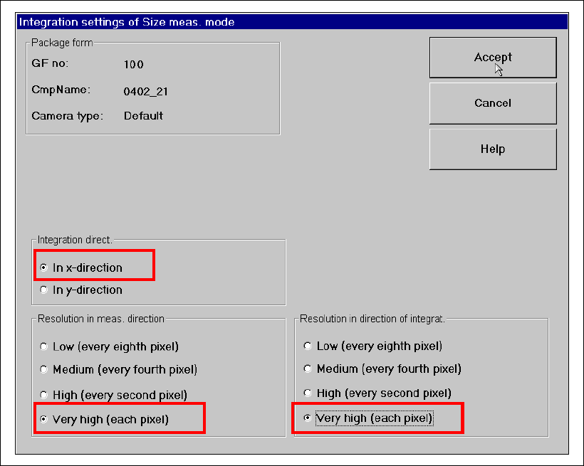
Å Click on the ‘Integration Settings’ button. The following options must be checked in the ‘Size
Measuring Mode, Integration Settings’ window:
– Integration direction in the X direction
– Resolution in meas. direction very high (every pixel)
– Resolution in direction of integration very high (every pixel)
Fig. 8 - 7 ‘Size’ measuring mode: Integration settings