OM-1455-004_w.pdf - 第79页
3-14 Tg1576-ID-SO 3. Component Library 3.1 Carrier Data This is a tab sheet which corresponds to all component shapes - "Cylindrical", "Square", "Deform", "IC (Simple)", "IC (…
3-13
Tg1576-ID-SO
2.1.2 Editing of Tray Step Information
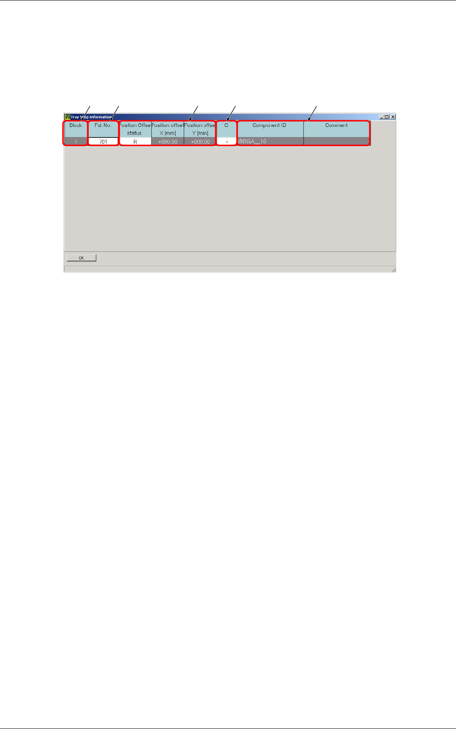
When a step No. is selected in the "Tray Step" edit window (Fig. C5-1), the
"Tray Step Information" window appears, enabling the operator to edit the
tray step information.
[1] [2] [4][3] [5]
Fig. C11 "Tray Step Information [1-15 Step]" Window
[1] Block
Shown are the block Nos.
[2] Fdr. No.
Displayed are the Nos. of the feeders arranged in each block.
[3] Position Offset status
Select "R", "L", or "Free Position" as Reference Point X for the block.
Position offset X [mm], Y [mm]
Enter the reference coordinates of the tray viewed from the pallet
reference position of each block.
[4] C
The control commands can be selected.
[5] Component ID and Comment
Displayed are the component IDs entered in the "Tray" edit window and
the comments entered in the component library data.
0711-002
2.1 Description of Pattern Program
3-14
Tg1576-ID-SO
3. Component Library
3.1 Carrier Data
This is a tab sheet which corresponds to all component shapes -
"Cylindrical", "Square", "Deform", "IC (Simple)", "IC (Complex)",
"Connector (Simple)", "Connector (Complex)", "Other Leaded (Simple)",
"Other Leaded (Complex)", and "BGA/CSP".
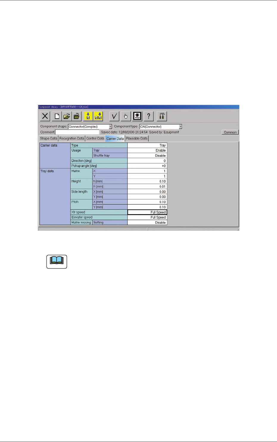
When the "Carrier Data" tab is pressed, the "Carrier Data" tab sheet appears.
Fig. C12 "Carrier Data" Tab Sheet (Type: Tray Selected)
Note
Refer to "2.3 (A03) Carrier Data" in "Chapter 2" of the instruction manual
"Component Library" for details of each data.
Set "Tray" in the "Type" text box of the label "Carrier data" and enter
parameters in the other text boxes of the label "Carrier data" and in the text
boxes of the label "Tray data".
0711-002
3. Component Library
3-15
Tg1576-ID-SO
4. System Setting
4.1 Offset Data
4.1.1 Unit Offset
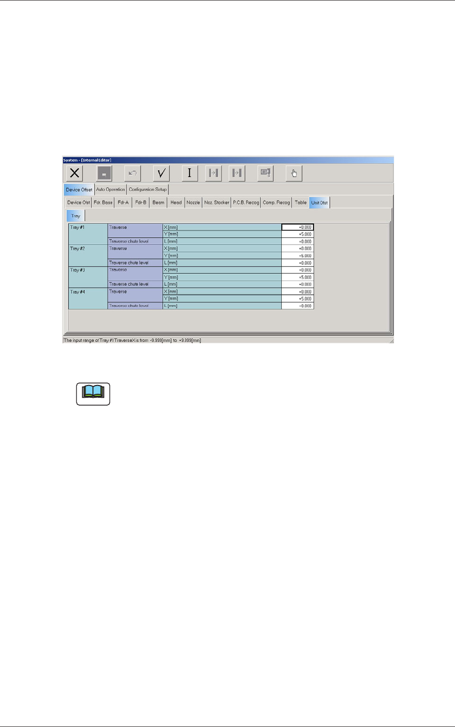
When the "Unit Ofst" subtab is pressed in the "Device Offset" tab sheet and
the "Tray" subtab is further pressed, the following subtab sheet appears.
Fig. C13 "Tray" Subtab Sheet
Note
The displayed subtab sheet will look different, depending on which option
is selected.
(1) Traverse
This offset is used to adjust the pallet drawing position.
X [mm] (Horizontal)
The set parameter is added to the beam travel when components are
picked up.
Y [mm] (Vertical)
The set parameter is added to the beam travel when components are
picked up.
(2) Traverse chute level
L [mm] (Height)
This offset data is used to adjust the level (height) of the pallet drawing
chute.
When a level lower than the design height is set, a plus value must be
entered in the text box.
0711-001
4. System Setting