AQ-2 spec book LR.pdf - 第28页
Options 26 of 44 A reject module is av ailable for components , which fail inspection because of pick -up errors or vision alignment. T wo reject possi bilities can be configured, one for inexpensive componen ts which ca…
Options
25 of 44
Figure 24
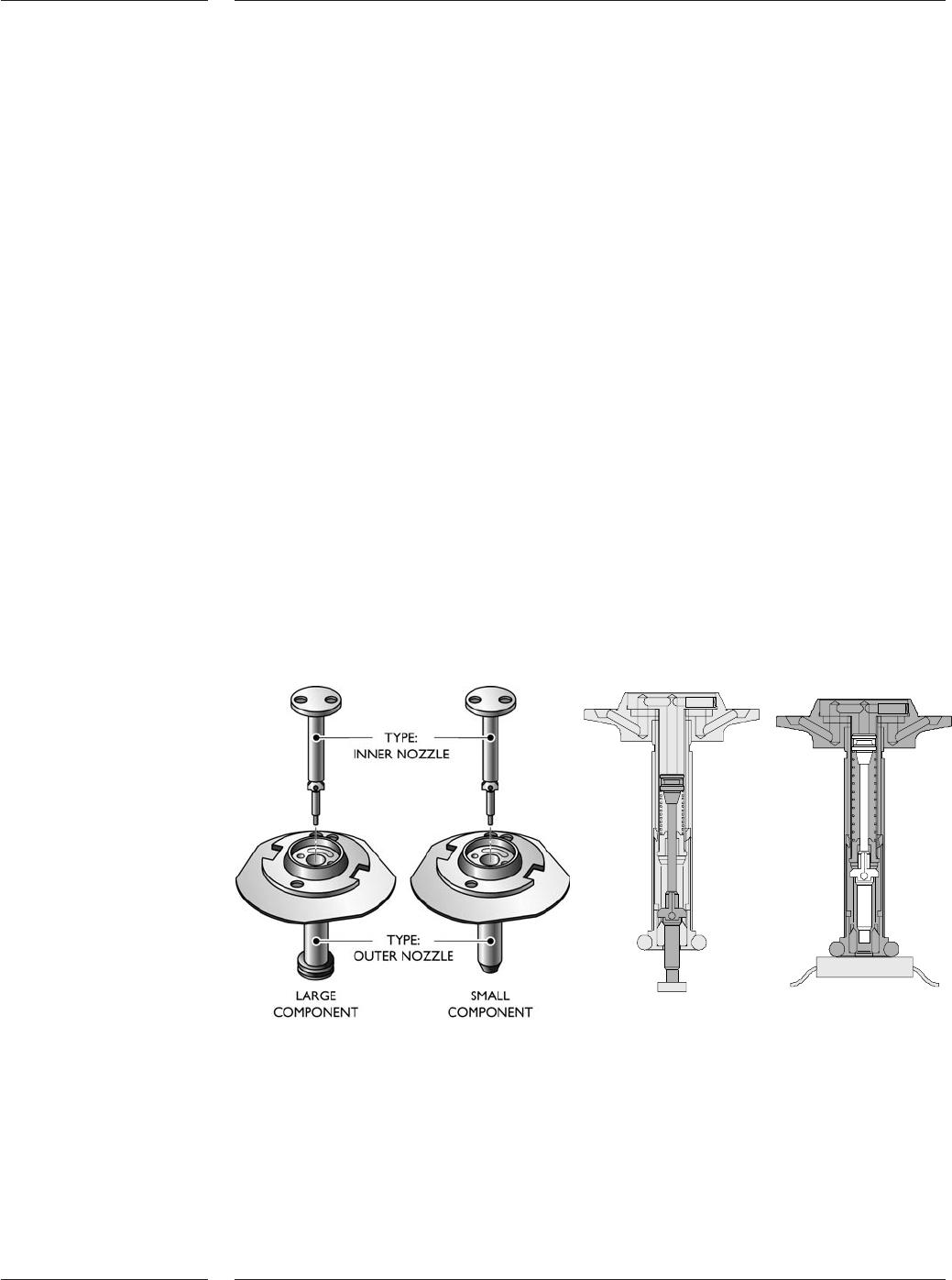
Inner and outer nozzles
Inner nozzle Outer nozzle
The AQ-2 has a wide variety of vacuum nozzles to pick and place components: standard
nozzles for a wide range of SMT components, odd component nozzles for odd shaped
parts, and low force nozzles for fragile components such as flip chips. It is important to
note that the standard nozzle design incorporates two nozzles in one. This is referred to
as ‘dual telescoping nozzles’. The AQ-2 has 4 different outer nozzles, each of different
diameters. Located inside the outer nozzle, a choice of up to 10 inner nozzles can be
used thereby allowing a wide range of components to be placed using the same
placement head. Time wasted as a result of nozzle exchanges is virtually eliminated.
AQ-2 nozzles are force controlled. The outer nozzles can be programmed between 4 and
40 N. The inner nozzles have a fixed force of 1.5 +/- 0.3 N.
The odd nozzles are especially designed to handle a wide range of odd components.
These nozzles are single nozzles with a programmable force between 4N and 40N.
Low forces nozzles are expecially designed for handling fragile components and can
place with forces downto 0.9N. Lower forces are possible upon special request.
The flip chip nozzles, used for semiconductor applications, are single nozzles and have a
programmable force ranging from 0.9N to 3.5N.
All AQ-2 nozzles can be exchanged manually or automatically using the toolbit
exchange unit.
See section 4.6 for a detailed description of all nozzles and the applicable component
range.
3.3 Toolbits
3.3.1 Nozzles
Options
26 of 44
A reject module is available for components, which fail inspection because of pick-up
errors or vision alignment. Two reject possibilities can be configured, one for
inexpensive components which can be discarded, another for expensive components
which need inspection and possible re-use. The required reject position can be
programmed by the user and specified per feeder or tray component.
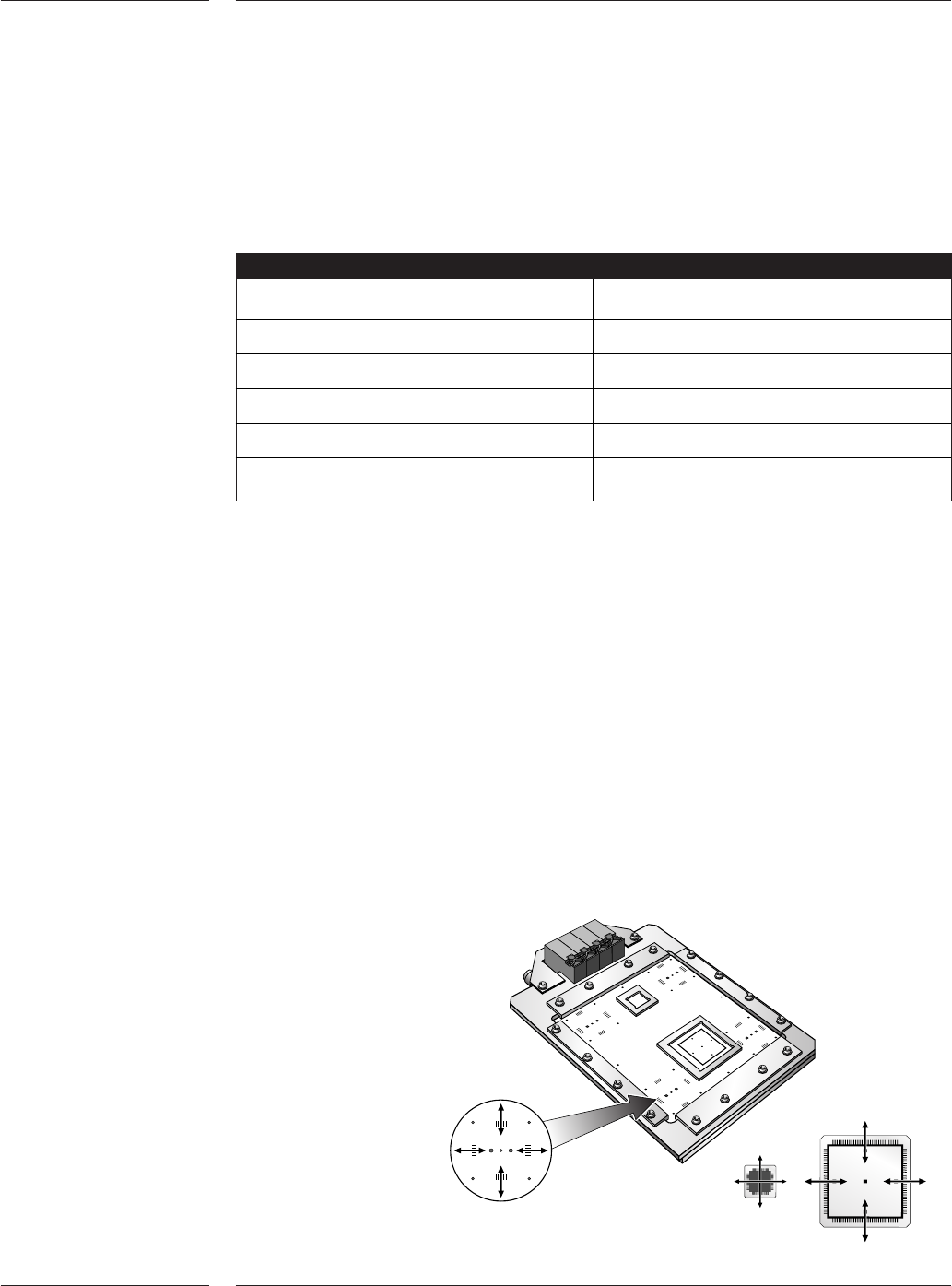
The accuracy verification set can be used to verify the accuracy of the placement
system by means of a glass board and glass components. The AQ-2 places the glass
components and measures the accuracy using the fiducial camera. The components are
placed under 4 different angles, and the user can define how many placements should
be done. Offset measurements are automatically calculated and can be used to
improve the calibration file of the AQ-2. This verification set is required to reach the
best possible accuracy of the AQ-2.
3.4 Reject
module
3.5 Accuracy
verification
set
Figure 25
Accuracy verification set
Mechanical grippers are available to pick and place components which cannot be
picked using vacuum nozzles. Depending on the application, outside in, or inside out
gripping can be selected. The standard gripper set contains a basic gripper with 3 jaw
sets that can be adapted by the user to comply with the specific shape of the
component being placed. The odd SMD gripper can be exchanged manually or
automatically, using the toolbit exchange unit.
Gripper
Max. component size 165 x 45mm
Max. component height 50mm
Max. weight 35 gram
Clamp force 6.5 ± 0.5N
Placement force 4 - 40N
Variable through hole check 4-14N
Table 21
3.3.2 Odd SMD
Grippers
Options
27 of 44
The standard language on the AQ-2 is English. However the operating system makes
on-line language switching possible. This means that with a simple keyboard
instruction the operator or engineer can switch between English and a local language,
including Asian languages. A wide range of languages is available, please contact
Assembléon for your specific language requirements. A software key will enable this
option.
All elementary production data is reported real-time:
•error occurrence (with detailed error information like feeder position, and measured
process variables like vacuum levels leading to the error)
•error solve information (operator actions)
• numbers of components picked and placed
All changes in machine processing mode are reported real-time. The machine uptime,
downtime, idletime etc. can be calculated by the host. All information can be reported
in listings or in graphs (optional). A software key will enable this option.
3.6 Multi
language
support
3.7 Real time
MIS data
3.8 Setup
Verification
System
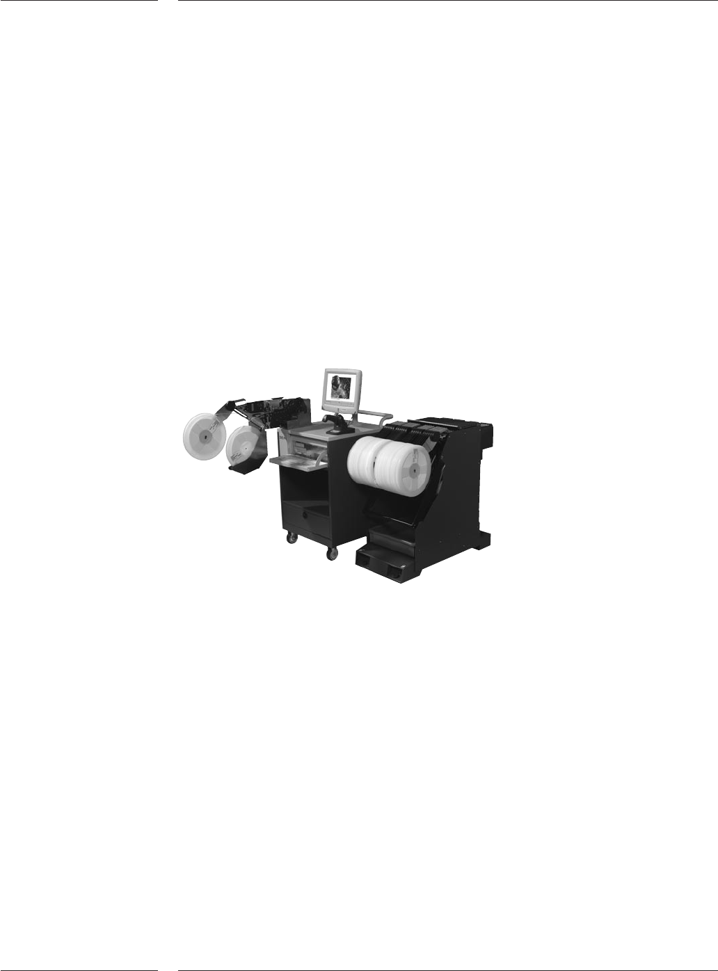
Figure 26
SVS-Pro offline programming station
The optional Setup Verification System (SVS-Pro) enables offline preparation and
verification of the feeder set-up on the feeder trolleys for FCM-Multiflex, AX-3, AX-5,
AQ-2, ACM Micro (NT version) and the GEM-Xi2 systems.
SVS-Pro takes advantage of the intelligence in the ITF-II feeders. Only one time reel-scan
is required, even if you move a feeder to a different position on the same or other
placement machine, plus even after ‘power down’.
Any possible set-up error can be corrected prior to the actual changeover using SVS-Pro.
The software helps to minimize the online changeover time from one to the other
production batch. It is also designed for ease-of-use in a frequent changeover
environment. In such cases SVS-Pro provides helps in offline set-up, the prevention of
set-up errors, pro-active pre-empty tape warnings and real-time set-up verifications.
SVS-Pro consists of two elements, an Offline Loading unit for the Feeder and Trolley
setup and verification, and the Machine specific part running on the placement
system(s). The Offline Loading Unit is a small trolley that conveniently can be moved
around the factory floor, for instance to be placed near the trolleys that needs to be
prepared for a next production batch. The Offline loading unit can be used for set-up
and verification of feeders and trolleys for FCM-Multiflex, AX-3, AX-5, AQ-2, ACM
Micro(NT version) and the GEM- Xi2 systems.