00193826-01.pdf - 第11页
User Manual SIPLAC E CS 1 Introduction Software vers ion SR.101.xx 06/ 2003 US Edition 11 1 Introduction These o perating instructi ons pro vide a ma nual or ref erence wo rk for – oper ati ng an d – setti ng up the plac…
Index of Figures User Manual SIPLACE CS
06/2003 US Edition
10
Fig. 3.11 - 5 Nozzle changer - position detection . . . . . . . . . . . . . . . . . . . . . . . . . . . . . . . . . . . . . . . . . . 97
Fig. 3.12 - 1 PCB conveyor. . . . . . . . . . . . . . . . . . . . . . . . . . . . . . . . . . . . . . . . . . . . . . . . . . . . . . . . . . . 98
Fig. 4.1 - 1 Dimensions of the placement system during transportation and setting up
in millimeters. . . . . . . . . . . . . . . . . . . . . . . . . . . . . . . . . . . . . . . . . . . . . . . . . . . . . . . . . . . 101
Fig. 4.3 - 1 Adjusting the component trolley to another PCB transport height . . . . . . . . . . . . . . . . . . 106
Fig. 5.4 - 1 Placing the tape in the springs of the S feeder. . . . . . . . . . . . . . . . . . . . . . . . . . . . . . . . . 113
Fig. 5.4 - 2 Inserting dividing plates in the component trolley tape container. . . . . . . . . . . . . . . . . . . 115
Fig. 5.4 - 3 Inserting spindles for large reels. . . . . . . . . . . . . . . . . . . . . . . . . . . . . . . . . . . . . . . . . . . . 116
Fig. 5.7 - 1 Pick-up position for components > 3 mm and </=3 mm . . . . . . . . . . . . . . . . . . . . . . . . . . 119
Fig. 5.7 - 2 Position of the component and its pick-up angle . . . . . . . . . . . . . . . . . . . . . . . . . . . . . . . 120
Fig. 5.9 - 1 Safety instructions on the component trolley . . . . . . . . . . . . . . . . . . . . . . . . . . . . . . . . . . 122
Fig. 5.9 - 2 Docking or undocking the component trolley . . . . . . . . . . . . . . . . . . . . . . . . . . . . . . . . . . 124
Fig. 5.10 - 1 Operating status indicator lamp . . . . . . . . . . . . . . . . . . . . . . . . . . . . . . . . . . . . . . . . . . . . 127
Fig. 6.2 - 1 8 mm S II feeder. . . . . . . . . . . . . . . . . . . . . . . . . . . . . . . . . . . . . . . . . . . . . . . . . . . . . . . . 132
Fig. 6.2 - 2 3 x 8 mm S feeder . . . . . . . . . . . . . . . . . . . . . . . . . . . . . . . . . . . . . . . . . . . . . . . . . . . . . . 133
Fig. 6.2 - 3 3 x 8 mm S feeder for 0201/0402 components. . . . . . . . . . . . . . . . . . . . . . . . . . . . . . . . . 134
Fig. 6.2 - 4 12/16 mm S feeder. . . . . . . . . . . . . . . . . . . . . . . . . . . . . . . . . . . . . . . . . . . . . . . . . . . . . . 135
Fig. 6.2 - 5 12 mm S feeder for capacitors based on powdered metal, model C/D . . . . . . . . . . . . . . 136
Fig. 6.2 - 6 12 mm S feeder for capacitors based on powdered metal, model E . . . . . . . . . . . . . . . . 137
Fig. 6.2 - 7 24/32 mm S feeder. . . . . . . . . . . . . . . . . . . . . . . . . . . . . . . . . . . . . . . . . . . . . . . . . . . . . . 138
Fig. 6.2 - 8 Linear vibratory feeder, type 3 . . . . . . . . . . . . . . . . . . . . . . . . . . . . . . . . . . . . . . . . . . . . . 139
Fig. 6.2 - 9 Bulk case feeder. . . . . . . . . . . . . . . . . . . . . . . . . . . . . . . . . . . . . . . . . . . . . . . . . . . . . . . . 140
Fig. 6.3 - 1 Inserting 30 or 45 mm wide feeders on the component table. . . . . . . . . . . . . . . . . . . . . . 142
Fig. 6.4 - 1 Component trolley. . . . . . . . . . . . . . . . . . . . . . . . . . . . . . . . . . . . . . . . . . . . . . . . . . . . . . . 143
Fig. 6.4 - 2 Component trolley with tape container . . . . . . . . . . . . . . . . . . . . . . . . . . . . . . . . . . . . . . . 144
Fig. 6.4 - 3 Compressed air supply for bulk case feeders. . . . . . . . . . . . . . . . . . . . . . . . . . . . . . . . . . 145
Fig. 6.4 - 4 Connecting the compressed air supply for bulk case feeders . . . . . . . . . . . . . . . . . . . . . 146
Fig. 6.4 - 5 Support for the middle tape reel for 3x 8 mm feeders . . . . . . . . . . . . . . . . . . . . . . . . . . . 147
Fig. 6.5 - 1 Used tape cutter . . . . . . . . . . . . . . . . . . . . . . . . . . . . . . . . . . . . . . . . . . . . . . . . . . . . . . . . 148
Fig. 6.5 - 2 Inserting the tape into the tape cutter. . . . . . . . . . . . . . . . . . . . . . . . . . . . . . . . . . . . . . . . 149
Fig. 6.5 - 3 Pull-out waste tape container in the component trolley . . . . . . . . . . . . . . . . . . . . . . . . . . 150
User Manual SIPLACE CS 1 Introduction
Software version SR.101.xx 06/2003 US Edition
11
1 Introduction
These operating instructions provide a manual or reference work for
– operating and
– setting up
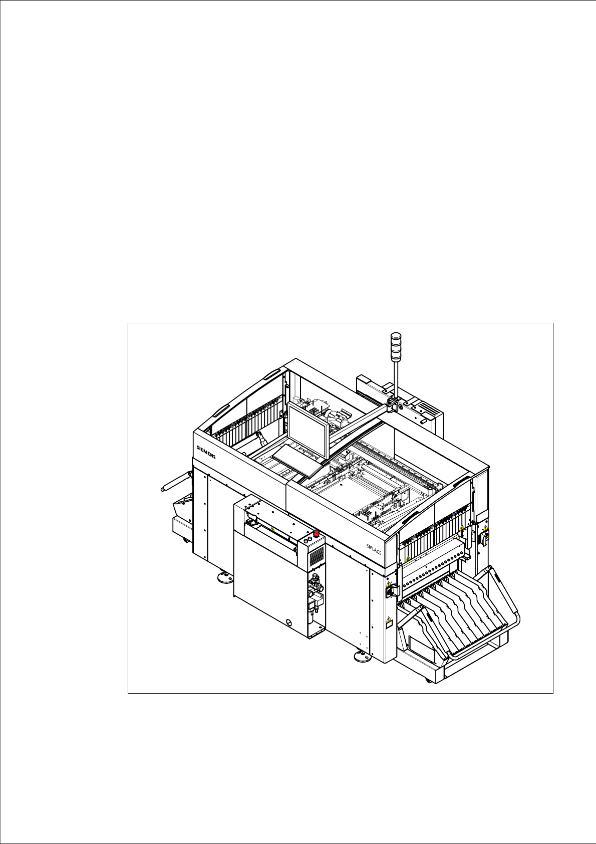
the placement system. 1
The header of each chapter contains the
– release and
– software version
to which this manual applies. 1
1
Fig. 1.0 - 1 SIPLACE CS placement system
1 Introduction User Manual SIPLACE CS
1.1 General Software version SR.101.xx06/2003 US Edition
12
1.1 General
1.1.1 How to get information
If you have any further questions concerning this manual or if you would like additional informa-
tion on a particular topic, please get in touch with your local Siemens dealer or contact us directly
at:
SIEMENSDEMATIC AG
Rupert-Mayer-Str. 44
D-81359 Munich 1
1.1.2 SIPLACE on the World Wide Web (WWW)
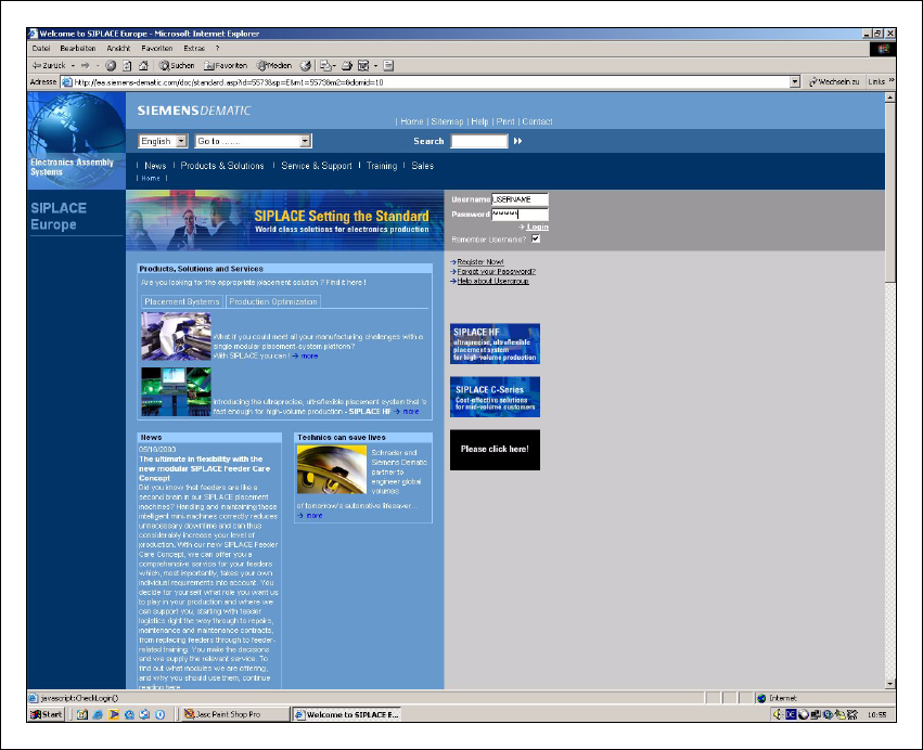
We also have our own site on the Internet. Why not log onto our SIPLACE home page at
http://www.siplace.com.
1
Fig. 1.1 - 1 The SIPLACE home page