00193826-01.pdf - 第88页
3 Technical data User Manual SIPLACE CS 3.10 Vision modules Software version SR.101.xx06/2003 US Edition 88 3.10.2 Component vision camera (st a ndard camera) on the 6-segment Collect &Place head 3.10.2.1 Structu re …
User Manual SIPLACE CS 3 Technical data
Software version SR.101.xx 06/2003 US Edition 3.10 Vision modules
87
3.10 Vision modules
3.10.1 Description
Each placement system has
– two component vision cameras on the placement heads and
– two PCB vision cameras on the underside of the X-axis gantries.
The vision analysis unit is located in the control unit for the placement system. The component
vision module is used to determine:
– the precise position of the components at the nozzle and
– the geometry of the package form.
The PCB vision camera uses fiducials on the PCBs to determine:
– the position of the PCB,
– its rotation angle
– and the PCB skew.
The PCB vision camera also uses fiducials on the feeders to determine the exact pick-up posi-
tion of components. This is particularly important for small components.
3 Technical data User Manual SIPLACE CS
3.10 Vision modules Software version SR.101.xx06/2003 US Edition
88
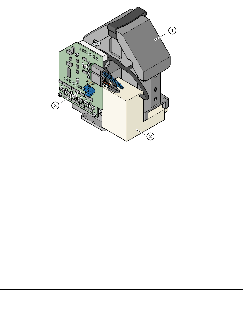
3.10.2 Component vision camera (standard camera) on the 6-segment
Collect&Place head
3.10.2.1 Structure
3
Fig. 3.10 - 1 Component vision camera on the 6-segment Collect&Place head
3
(1) Component camera, lens and illumination
(2) Camera amplifier
(3) Illumination control
3.10.2.2 Technical data
3
Max. component dimensions 0.6 mm x 0.3 mm to 18.7 mm x 18.7 mm
Range of components 0201 to PLCC44
including BGA, µBGA, flip-chip, TSOP, QFP
PLCC, SO to SO32, DRAM
Min. lead pitch 0.5 mm
Minimum bump pitch 0.35 mm
Min. ball/bump diameter 0,2 mm
Field of vision 24 mm x 24 mm
Method of illumination Front-lighting (3 levels programable as required)
User Manual SIPLACE CS 3 Technical data
Software version SR.101.xx 06/2003 US Edition 3.10 Vision modules
89
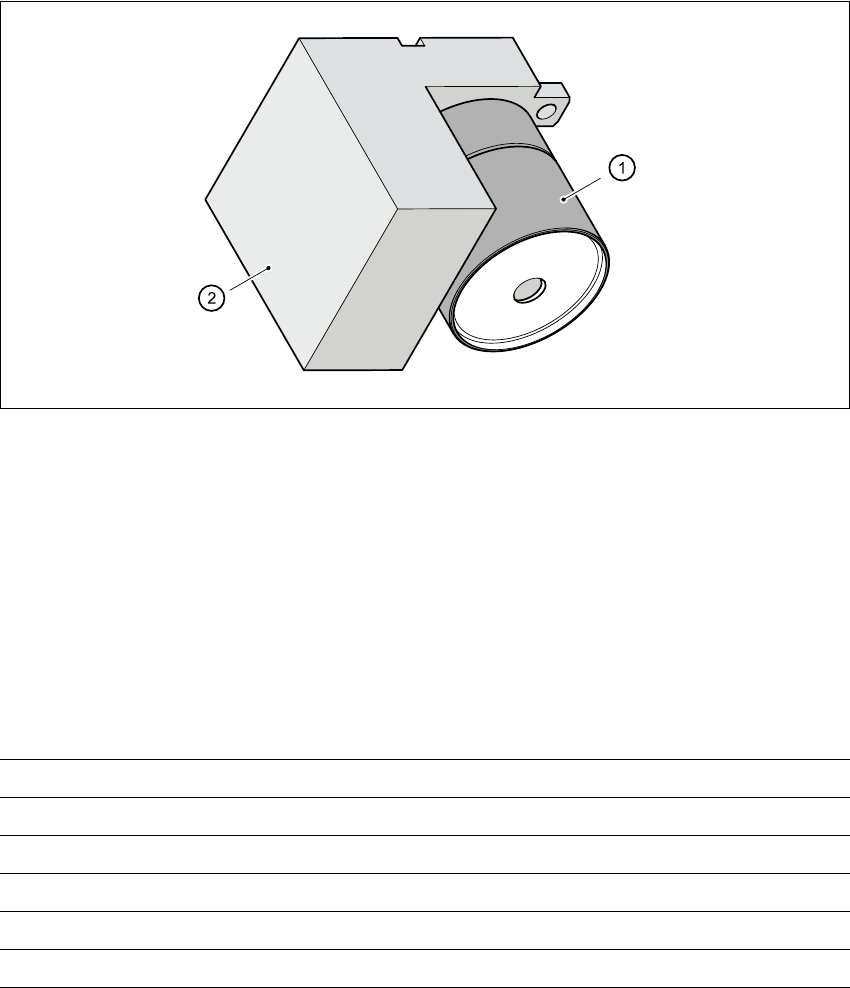
3.10.3 PCB vision camera (standard camera)
3.10.3.1 Structure
3
Fig. 3.10 - 2 PCB vision camera (standard camera)
3
(1) PCB camera, lens and illumination
(2) Camera amplifier
3.10.3.2 Technical data - PCB vision camera
3
Fiducials Up to 3 per placement program
Library size Up to 255 fiducial types - system fiducials 249
Image processing Geometric alignment
Method of illumination Front-lighting
Recognition time per fiducial/bad fiducial 0.4 s
Field of vision 5.7 mm x 5.7 mm