00193826-01.pdf - 第42页
2 Operational safety User Manual SIPLACE CS 2.5 Safety equipment Software version SR.101.xx06/2003 US Edition 42 2.5 S afety equipment 2.5.1 Protectiv e cove rs Fig. 2.5 - 1 Safety eq uipment in the placement m achine (1…

User Manual SIPLACE CS 2 Operational safety
Software version SR.101.xx 06/2003 US Edition 2.4 Safety instructions for operating the machine
41
The feeders are labeled as shown below:
2
WARNING FIRE HAZARD 2
Æ Check and empty the waste tape container every hour.
Æ Only empty the waste tape container into suitable collection containers because of the risk of
fire. These containers must not be set up inside buildings.
Approved for
capacitors based on
metal-powder
Freigegeben für
Kondensatoren auf
Metallpulver-Basis
2 Operational safety User Manual SIPLACE CS
2.5 Safety equipment Software version SR.101.xx06/2003 US Edition
42
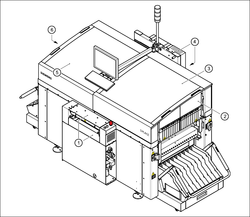
2.5 Safety equipment
2.5.1 Protective covers
Fig. 2.5 - 1 Safety equipment in the placement machine
(1) Cover and guard on the input belt
(2) Safety panels, right-hand side
(3) Protective cover
(4) Cover and guard on the output conveyor
(5) Protective cover
(6) Safety panels, left-hand side
User Manual SIPLACE CS 2 Operational safety
Software version SR.101.xx 06/2003 US Edition 2.5 Safety equipment
43
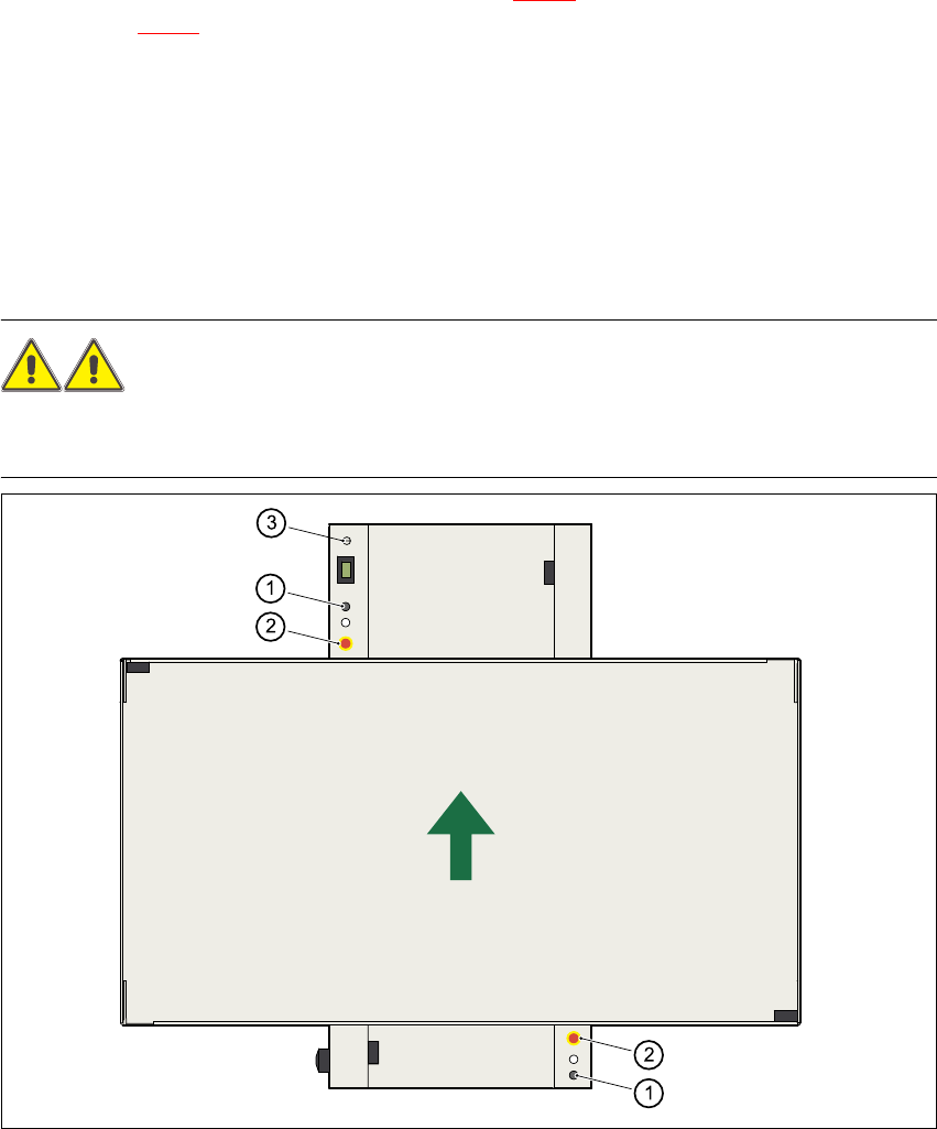
2.5.1.1 General
The gantry positioning range is covered by two protective covers. If you want to open the protec-
tive covers, first press the Stop button (item 1 in Fig. 2.5 - 2
) or the EMERGENCY STOP button
(item 2 in Fig. 2.5 - 2
). The power to the gantry axes will be switched off and the gantries will stop
immediately. If you open one of the protective covers or a guard on the incoming or outgoing con-
veyor, the power to the gantry axes will be switched off. They will stop immediately.
If the key switch is closed (position I), you can continue to pace the star at reduced speed while
the protective covers are open.
Placement will stop if you press the EMERGENCY STOP button. You can then either cancel or
continue placement of the PCB. The protective covers at the sides can be opened in order to
refill with components when the machine has stopped.
WARNING
The protective covers must only be opened, with the key switch closed (position I), by appropri-
ately qualified and trained personnel. 2
Fig. 2.5 - 2 Stop and EMERGENCY STOP buttons
(1) Stop button
(2) EMERGENCY STOP button
(3) Key-operated switch