00193826-01.pdf - 第140页
6 Component handling User Manual SIPLACE CS 6.2 Technical data f or the feeders Software version SR. 101.xx06/2003 US Edition 140 6.2.9 Bulk ca se fee der 6 Fig. 6.2 - 9 Bu lk case feeder Part no. 0014231 8-xx 6 Width 29…
User Manual SIPLACE CS 6 Component handling
Software version SR.101.xx 06/2003 US Edition 6.2 Technical data for the feeders
139
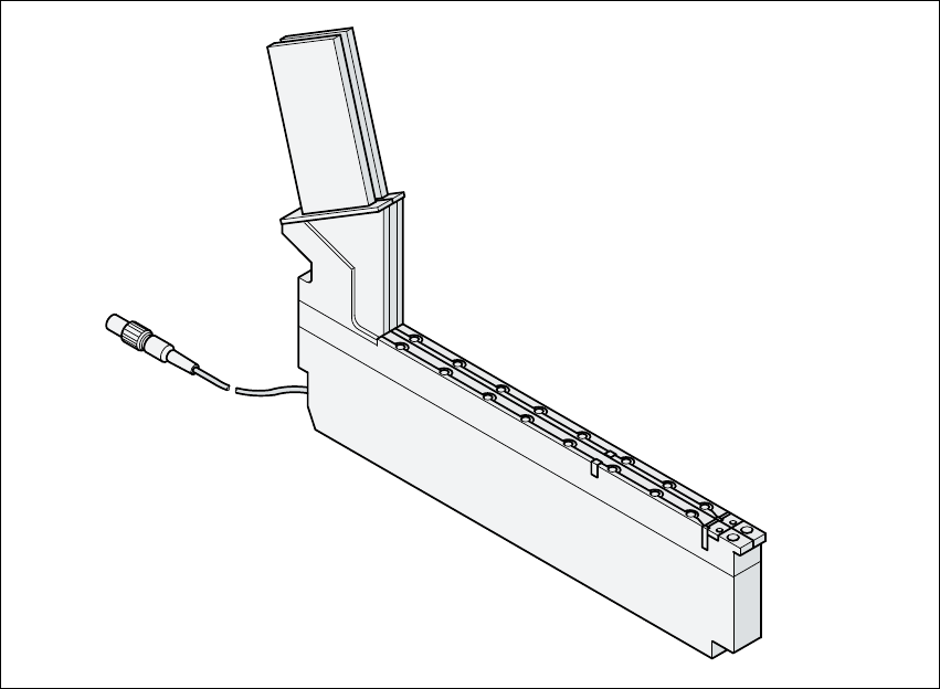
6.2.8 Vibratory stick feeder, type 3
Fig. 6.2 - 8 Linear vibratory feeder, type 3
Part no. 00142031-xx 6
Width 28 mm 6
Tracks per feeder 1, 2, 3, or 6 6
Assigned locations 1 6
Maximum number of feeders 2 x 20 6
Stock of components up to 150 per steel stick magazine, 6
depending on the component length 6
Specific data for stick magazines 9.5 mm wide / x 3 6
15 mm wide / x 2 6
> 15 mm wide / x 1 6
30 mm wide / x 1 6
Cycle time (variable) from 400 to more than 1000 msec 6
6 Component handling User Manual SIPLACE CS
6.2 Technical data for the feeders Software version SR.101.xx06/2003 US Edition
140
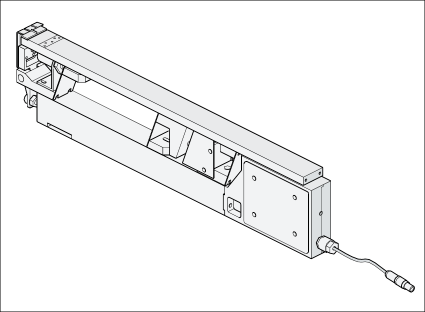
6.2.9 Bulk case feeder
6
Fig. 6.2 - 9 Bulk case feeder
Part no. 00142318-xx 6
Width 29 mm 6
Tracks per feeder 2 6
Assigned locations 1 6
Maximum number of feeders 2 x 20 6
Stock of components up to 50,000 6
Feeding rails 0402 / 0.35 mm high part no. 00142319-xx6
0402 / 0.5 mm high part no. 00142320-xx6
0603 / 0.45 mm high part no. 00142321-xx6
0603 / 0.80 mm high part no. 00142322-xx6
0805 / 0.45 mm high part no. 00142323-xx6
0805 / 0.60 mm high part no. 00142324-xx6
0805 / 0.85 mm high part no. 00142325-xx6
0805 / 1.25 mm high part no. 00142326-xx6
Micro Melf / 1.05 ± 0.05 mm part no. 00142327-xx6
Mini Melf / 1.40 ± 0.1 mm part no. 00142328-xx6
Cycle time < 60 ms 6
User Manual SIPLACE CS 6 Component handling
Software version SR.101.xx 06/2003 US Edition 6.3 Setting up the feeders
141
6.3 Setting up the feeders
6.3.1 Preparing the component table and feeder for set-up
Æ Select the setting range for the feeder to be used (see Vibrator configuration).
Æ Move the placement head to the waiting position and press the emergency stop button.
Æ Open the protective covers.
Æ Clean the contact surface for the feeders and the contact surface for the feeders on the com-
ponent table.
RISK OF INJURY
Avoid removing components from the magnetic rail of the component table with your fingers.
You may hurt yourself with tiny splinters of metal. 6
Æ Remove loose components with a short-bristled brush.
Æ Handle the feeders carefully when you insert them into or remove them from the component
table. Do not allow the supporting surfaces of the feeders to bang against the edges of the
component table.
Æ Place the feeder on the previously selected track on the component table (see Vibrator config-
uration).
6.3.2 Inserting the feeder
Æ Insert the feeder so that the back of the feeder is held by the centering ball and the front is fixed
in place by the corresponding centering pin on the component table. Make sure that the feeder
is placed on the component table in the correct position for its width.
Æ Check that the feeder is firmly seated on the component table.
Æ Connect the feeder plug to the socket beneath the location.
PLEASE NOTE 6
When you connect the feeder, make sure that you use the right socket for the location since
the feeder receives the control pulse via this socket. The feeder may not work correctly if it
is not connected to the right socket. 6