00193826-01.pdf - 第67页
User Manual SIPLAC E CS 3 Technical data Software vers ion SR.101.xx 06/2003 US Edition 3.3 Electrical and pneumatic connection p oints 67 3.3 Electrical and pneumatic con nection po int s 3 Fig. 3.3 - 1 Electrical and p…

3 Technical data User Manual SIPLACE CS
3.2 The line concept Software version SR.101.xx06/2003 US Edition
66
3.2 The line concept
3.2.1 Overview
Up to 5 placement machines from the SIPLACE Compact families can be linked to form a line.
3.2.2 Technical data – line concept
3
System SIPLACE placement lines
Modules SIPLACE CS, SIPLACE CF
Peripherals Input/output stations
Screen printers
Soldering ovens
Inspection stations, etc.
Component range From 0201 to 18,7 mm x 18,7 mm (CS)
From 0201 to 55 mm x 55 mm (CF)
PCB conveyor Automatic width adjustment
PCB format (length x width) 50 mm x 50 mm to 508 mm x 460 mm
(2" x 2" to 20" to 18")
Placement rate Depends how modules are connected in series
Line software SIPLACE C Pro
Space required 4 m² / module
User Manual SIPLACE CS 3 Technical data
Software version SR.101.xx 06/2003 US Edition 3.3 Electrical and pneumatic connection points
67
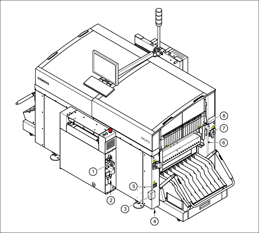
3.3 Electrical and pneumatic connection points
3
Fig. 3.3 - 1 Electrical and pneumatic connection points on the placement system part 1
3
(1) Compressed air unit
(2) Connection for compressed air line
(3) Main power filter Z1
(4) Hole for power cable
(5) Service socket
(6) Compressed air connection for component trolleys
(7) Power supply connection for component trolley
(8) Communications connection for component trolley
3 Technical data User Manual SIPLACE CS
3.3 Electrical and pneumatic connection points Software version SR.101.xx06/2003 US Edition
68
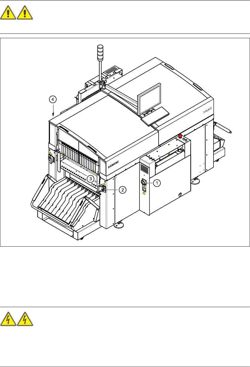
WARNING
Never disconnect compressed air lines while they are pressurized. Risk of injury! 3
Fig. 3.3 - 2 Electrical and pneumatic connection points on the placement system part 2
(1) Main power switch
(2) Power supply connection for component trolley
(3) Communications connection for component trolley
(4) LAN connection (RJ45) in the control unit 45
WARNING
The placement system is supplied with 3 x 400 V~ or 3 x 208 V~ US version) ± 5%, 50/60 Hz
main power voltage. This means that some parts of the system carry potentially lethal voltages
- even when switched off at the main power switch. Death, serious injury or considerable damage
may result if this automatic placement system is handled incorrectly. 3