00197044-02_IM_706_1_DE_EN.pdf - 第48页
Station S oftware 706. 1 / Install ation Man ual Ausgabe 11/2012 E dit ion 48 W hen you have se lected a ll tab le config urations the fol lo wing wind ow is disp la yed, in w hich you confirm the Auto - configur ation. …
Station Software 706.1 / Installation Manual Ausgabe 11/2012 Edition
47
► Click the Accept button.
► Repeat the steps for Location 1.
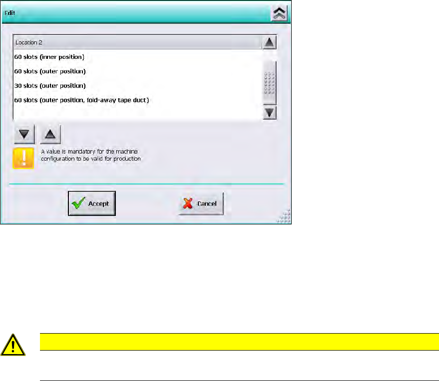
Settings for manual tray Carrier SX
If the manual tray Carrier SX is used, the insert frame with the fold-away tape guide channel is
required. This has to be set manually. In this case, the following selectable table configurations are
displayed:
Figure 7-8: Settings for manual tray Carrier SX
► Select the 60 slots (outer position, fold-away tape duct) table configuration.
► Click the Accept button.
Thus, the 27x27 reject bin and the left reject channel on the location are excluded from the
configuration.
CAUTION
If this setting is not made, the component may be rejected over the tray and the Z axis
may dash hard against the tray.
► Repeat the steps for Location 1.
Station Software 706.1 / Installation Manual Ausgabe 11/2012 Edition
48
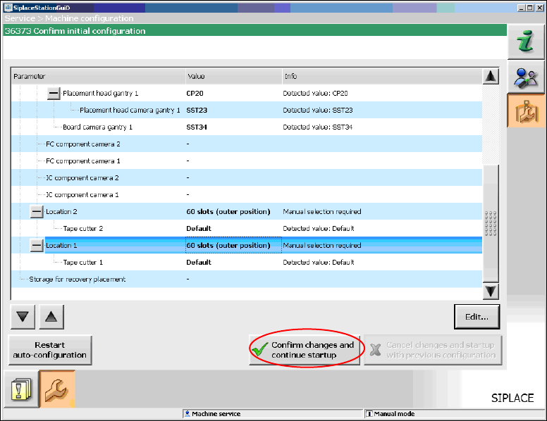
When you have selected all table configurations the following window is displayed, in which you
confirm the Auto-configuration.
Figure 7-9: Confirming Auto-configuration for SX1/SX2
► Click the Confirm changes and continue startup button to confirm the Auto-configuration.
► If the Coplan computer has been installed, you will additionally have to confirm or reject the 3-D
Coplan sensor.
7.4 SX+ Placement Machine
If the SX+ placement machine is to be used without gantries, this has to be configured in the Auto-
configuration after the machine has been booted.
► For this, select Ignore gantries at the processing area in the machine configuration dialog.
Station Software 706.1 / Installation Manual Ausgabe 11/2012 Edition
49
7.5 SX4 Placement Machine
► When the SX4 placement machine is booted for the first time you have to select the SX4
Flexible entry for Machine frame manually in the Auto-configuration, if there are tables in
outer position in processing area 2, as this is not detected automatically via sensors.
Tables in outer position are used when stationary cameras are in use.
► Otherwise you select the SX4 High Speed entry.
7.6 DX-Series Placement Machines
► When the DX placement machines are booted for the first time you have to select the following
options manually:
– For C&P12 placement head: height position (altitude)
– Lamp indicators (two-colored or three-colored)
– Table position:
inner 60 tracks
outer 60 tracks
outer with 30 tracks + free location for tray or WPC
– Confirm/reject 3-D Coplan sensor
7.7 Checking/Updating the Embedded Software
If the correct eSW versions are not available on the machine, the machine boot gets interrupted.
► In this case, perform an eSW download.
► Start an overall reference run for the machine.
7.8 Storage Location of the Machine Files (Calibration Data etc.)
The machine-specific configuration, measurement and parameter data is stored in XML files under
C:\Sirio\Work\Individual. These XML files contain all the calibration data.