6241f.pdf - 第10页
Page 2 GS-394-02 Operator Push Button Panel The PB panel includes the Emergency-Stop switch, the Interlock Reset button, the Start and Stop buttons, the Override or Transfer Error button, and the Interlock Bypass Key Swi…
Page 1GS-394-02
Introduction
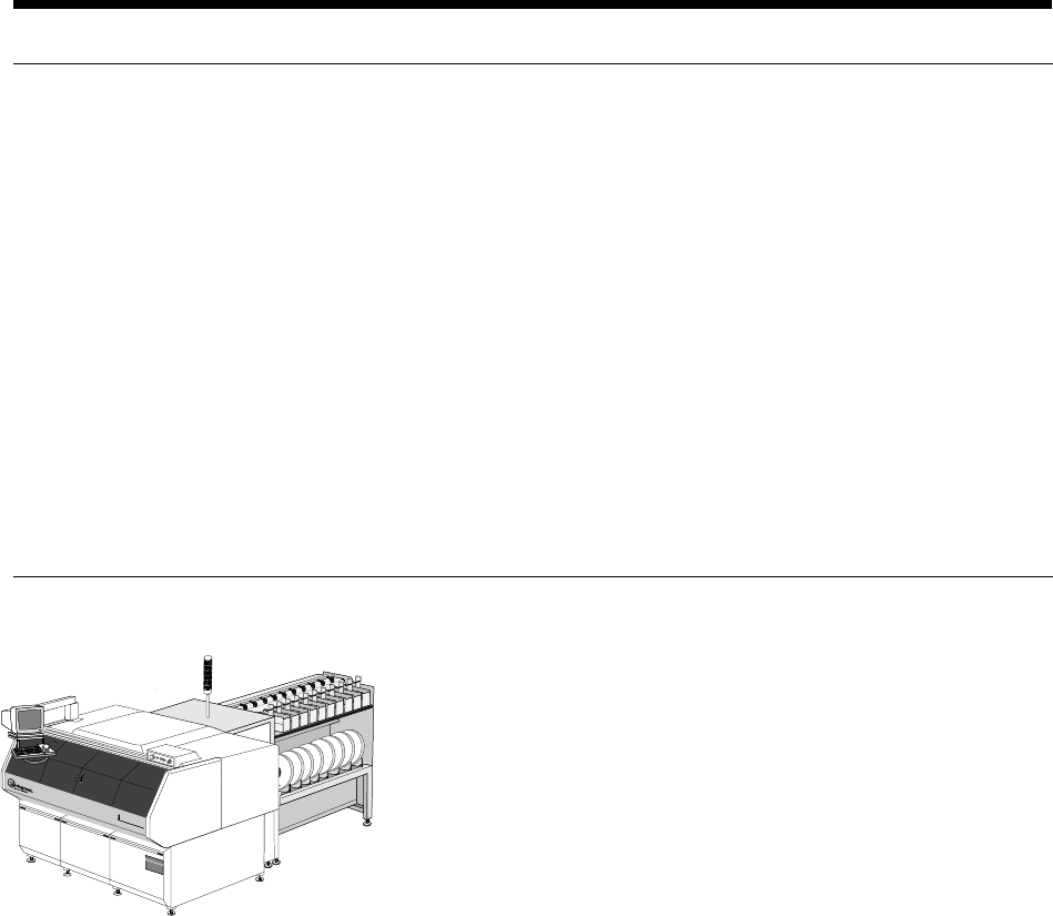
The VCD/Sequencer 8 (Model 6241F) automatically sequences and
inserts class A—52mm axial leaded components into printed circuit
boards (PCB).
The VCD/Sequencer 8 is available with automatic PCB handling,
Loader/Unloader. See Appendix A for Board Handling details
(Mag-to-Mag, Raw Card-to-Mag and Destacker-to-Mag).
Insertion rates up to 25,000 components per hour can be achieved by
the VCD/Sequencer 8. (See “Insertion Rate Determination.”)
Selected configurations of the VCD/Sequencer 8 are CE marked.
Functional Description
The VCD/Sequencer 8 is a single head axial lead component
sequencer/inserter that automatically inserts components from taped
input into printed circuit boards (PC boards). A product (pattern
program) is created with information pertaining to the components,
PC boards, and processing requirements. When this product is
loaded, machine operation can be started.
The VCD/Sequencer 8 sequencer modules contain dispensing heads
which cut axial lead components from input tape reels or ammo packs
and place them on the sequencer chain. The component sequence is
predetermined by a pattern program (product). The components are
then transferred to the VCD head chain for delivery to the insertion
tooling. The pattern program controls the location and orientation of
component insertion.
After insertion through the PC board, the component leads are cut
and formed (clinched) to mechanically secure them to the board. The
process continues until the product is completed and all required
axial components are in place. When the pattern program is com-
plete, the PC board is removed or transferred from the machine.
Page 2 GS-394-02
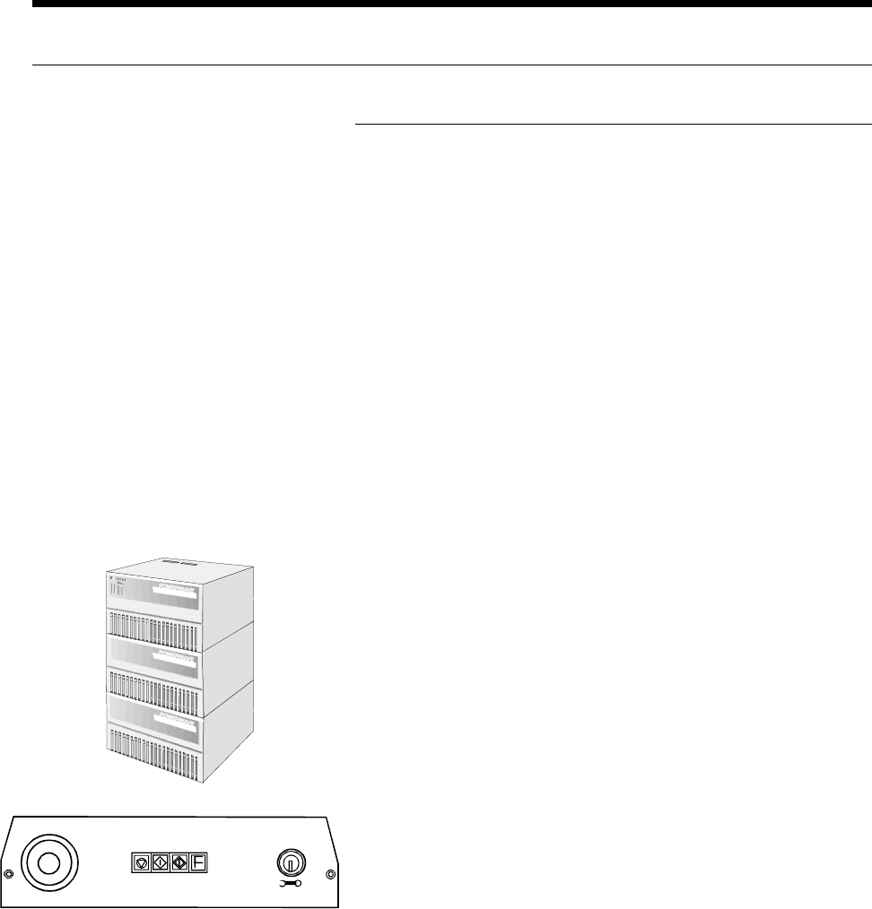
Operator Push Button Panel
The PB panel includes the Emergency-Stop switch, the Interlock
Reset button, the Start and Stop buttons, the Override or Transfer
Error button, and the Interlock Bypass Key Switch. All other
machine functions are accessed through the graphical user interface
via the keyboard, trackball, and monitor.
Rear Start/Stop Switches
Start/stop switches are located at the transfer cabinet adjacent to
Sequencer Module 1 and at the last sequencer module. These are
conveniently located to minimize downtime when reloading compo-
nents.
Standard Features
Machine Control System
VME Machine Controller
The VME machine controller is a rack-mounted multi-processor
system with an embedded Intel-based P.C. to support the main
operator interface. The operator interface is provided through a
color monitor, keyboard, and trackball. The main machine controller
is a Power P.C.-based unit, which handles all machine functions and
timing.
Two four-axis micro-processor based motion controllers are used
for Positive Axis Control (PAC) of the insertion head, cut and clinch,
sequencer chain drive, and X-Y positioning system. A third four-
axis motion controller is used with the optional loader/unloader.
Uninterruptible Power Supply (UPS)
External to the machine, the Uninterruptable Power Supply provides
filtered, stable, and continuous power of 230 VAC to the machine.
In the event of a power interruption, its fully-charged battery can run
the machine for up to 10 minutes. This allows time for a controlled,
orderly, manual shut-down of the machine.
STOP START
OVERRI DE/
TRANSFER
ERROR
INTAKE
RESET
OFF
REMOVE
ON
INTERLOCK
BYPASS
Page 3GS-394-02
Network Kit
Standard with each machine is a package for computer network
connection capability that includes an Ethernet network card and
IBM OS/2 TCP/IP client software. This provides high speed,
reliable communications and data transfer to all computers con-
nected to the network.
Board Error Correction (BEC)
Board Error Correction allows the positioning system to compensate
for lead hole location variations between printed circuit board lots.
A light source and sensor are used to sense the variation and make
these corrections.
Operator
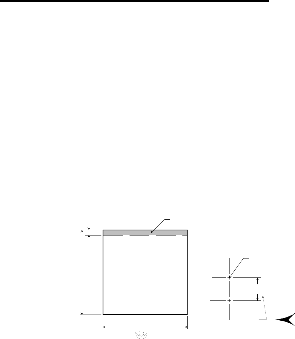
Board Error Correction Detection Area
Due to the position of the Board Error Correction sensor relative to
the insertion point, there is an area which cannot be scanned by the
sensor. The non-scannable area is at the rear of the positioning
system regardless of rotary table rotation.
This area cannot be scanned by
Board Error Correction Sensor.
22.86mm
(0.900")
470mm
(18.5")
508mm (20.0")
Dimensions are in millimeters;
inch equivalents are bracketed.
+Y
Insertion
Centerline
BEC Sensor
Offset
+X
22.86mm
(0.900")