6241f.pdf - 第14页
Page 6 GS-394-02 BOM-CAD Link: A user-defined alphanumeric string which links a line of data in the CAD file to a component ID in the Bill of Material (BOM) file. Ignore: If the CAD file contains data that does not fit a…
Page 5GS-394-02
Machine Status Icon
Management Information Icon
IM Diagnostics Icon
On-Line Documentation Icon
Machine Status
• Current Messages — Displays current controller messages and
events.
Product Status — Displays status of running product.
• Analytic Information:
• Discrete I/O — Ability to read each input and set each
output individually.
• Message History — Ability to view message log.
• Operations — Sets machine modes: Step, Single Cycle, Insert,
Pattern.
• Error Recovery — Recovery processes for operational errors,
i.e., mis-insertion.
Management Information
• Timers — Collection and display of machine timers.
• Counters — Count of machine events: insertions, insert errors,
boards, Bad Board Reject, Board Error Correction, circuits.
• Component Data — Counts by component ID: placements,
errors.
From these databases, a variety of reports can be created.
IM Diagnostics
• IM Diagnostics — Ability to exercise machine sub-systems on
an individual or combined basis outside of machine control
software.
• B.E.C. Set-Up/Analysis.
• Machine Set-Up Support.
On-Line Documentation
• IM-UPS documentation is available on-line.
Page 6 GS-394-02
BOM-CAD Link: A user-defined alphanumeric string
which links a line of data in the CAD file to a component ID
in the Bill of Material (BOM) file.
Ignore: If the CAD file contains data that does not fit any of
the fields, IM-UPS may be configured to ignore this data.
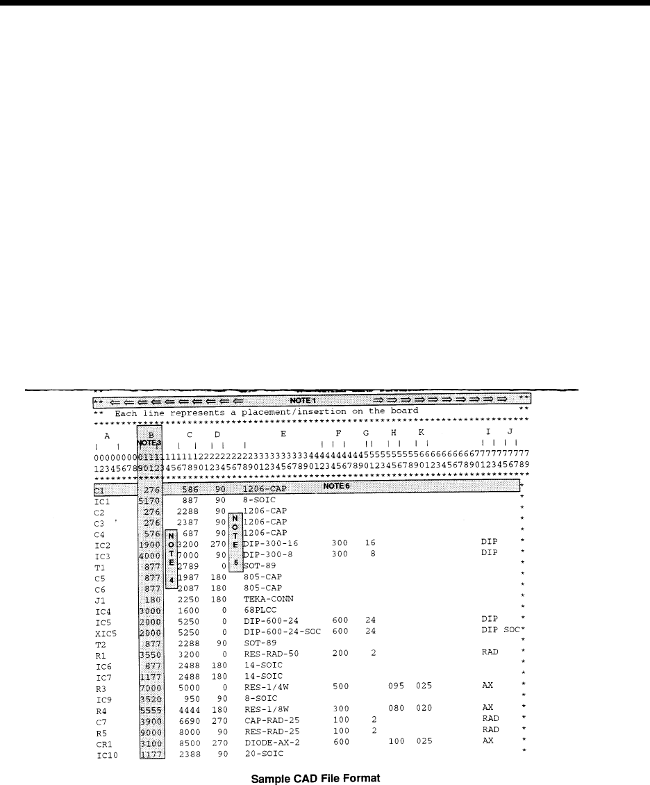
A sample CAD file format is given with a brief explanation.
This file format is provided for reference only and is an ex-
ample of a typical CAD output.
CAD Data Requirements
ASCII File Format — Incoming CAD files must conform to the
American National Standard Code for Information Interchange
(ASCII). In order to accommodate a wide variety of CAD file
formats, the APE uses either a generic columnar or separator
data translation technique. All data contained in the CAD file
is identified by a position in a definition created by the user.
CAD File Requirements
X Coordinate: The X centroid coordinate location on the
board.
Y Coordinate: The Y centroid coordinate location of the
component insertion.
Theta: The rotation of the component on the board.
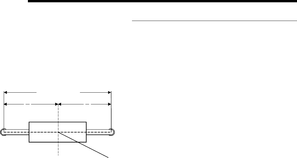
Insertion Lead Span: The distance between the centerlines
of the component leads.
Reference ID: The name assigned to the component makes
it unique to all other components in the product.
Component ID: The name of the component as it is found in
the component database.
Alias ID: The name of a component in the database to which
this component is aliased (optional).
Centroid (Top View)
Length = "L"
L
2
L
2
X, Y
Page 7GS-394-02
This is a typical CAD file which may be output from a wide variety of different CAD systems.
This file includes SMC and IMC information, with component information stored for the IMC components.
The component information for Surface Mount components will be obtained from the master .DEF files.
IMC component information will be obtained from this file and placed into the Component Library.
Information in the CAD file:
A = REFERENCE DESIGNATOR F = SPAN
B = X COMPONENT CENTROID COORDINATE G = NUMBER OF LEADS
C = Y COMPONENT CENTROID COORDINATE H = AXIAL BODY DIAMETER
D = ORIENTATION I = MACHINE TYPE
E = PART NUMBER/COMP ID J = DIP SOCKET
K = AXIAL LEAD DIAMETER