6241f.pdf - 第37页
Page 29 GS-394-02 Insertion Specifications Type VCD (Variable Center Distance) Hole Span Minimum Maximum Standard Tooling 7.62mm (0.300") 24.13mm(0.950") 5.0mm Tooling 5.0mm(0.197") 21.59mm(0.850") Pr…
Page 28 GS-394-02
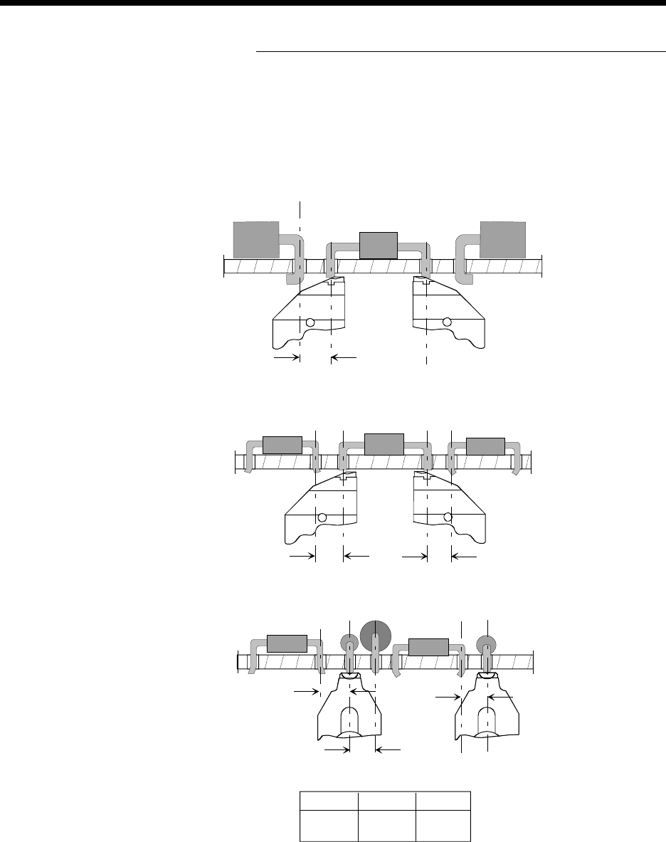
Component Clearances for Cut and
Clinch Anvil Assemblies
Side View
Axial leaded components
to previously inserted
axial leaded components.
Side View
Axial leaded components
to previously inserted
DIP components, with both
outward and inward clinch.
End View
Axial leaded components
to previously inserted
axial leaded and DIP
components shown with both
outward and inward clinch.
A B C
3.68mm 2.54mm 2.54mm
0.125" 0.100" 0.100"
A
B
C
2.54 (0.100)
2.79 (0.110)
2.54 (0.100)
Outward DIP
Inward DIP
Outward DIP
Inward DIP
Continuity Style Lead Sense
Dimensions are in millimeters;
inch equivalents are bracketed.

Page 29GS-394-02
Insertion Specifications
Type VCD (Variable Center Distance)
Hole Span Minimum Maximum
Standard Tooling 7.62mm (0.300") 24.13mm(0.950")
5.0mm Tooling 5.0mm(0.197") 21.59mm(0.850")
Programmable 0.01mm (0.001")
Span Increments
Depth Stops Programmable from 0.2mm to 5.28mm (0.008"
to 0.208") in 0.2mm (0.001") increments.
Board to Tooling 20mm (0.8") maximum with tooling in full up
Clearance position
Cut and Clinch Adjustable from 45° to 90° clinch angle.
Insertion Rate Up to 25,000 insertions per hour with factory test
specifications. Refer to Insertion Rate
Determination section.
Positioning System
Accuracy ±0.05mm (±0.002")
Repeatability ±0.025mm (±0.001")
Table Capacity 22.7 kg (50 lbs) maximum, including
workboard holder
Programming ±0.01mm (metric dimensioning)
Capability ±0.001" (inch dimensioning)
Speed 368mm (14.5") per second
Sequencer Specifications
Input Class I (52mm), standard. Per EIA Standard
RS-296-E and this General Specification. Also,
limited class II. See “Input Specification.”
Dispensing Heads Required, must be ordered separately. Refer to
the Optical Refire Dispensing Head section.
Sequencer Up to 11 sequencer modules in multiples of 20
Modules dispensing stations (220 stations maximum);
two optional jumper wire dispensing heads can
be installed.
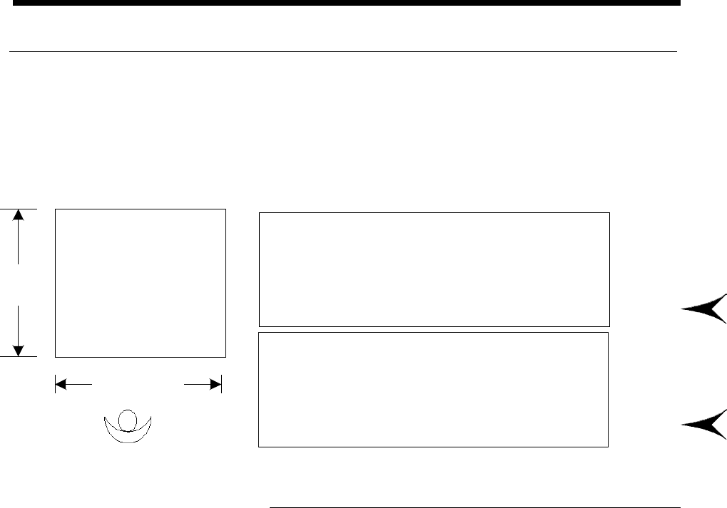
Page 30 GS-394-02
Printed Circuit Board Specifications
PC boards must meet the requirements outlined below.
• Minimum Board Thickness: 0.79mm (0.0312").
• Maximum Board Thickness: 2.36mm (0.0937").
• Allowable Board Dimensions: See tables below.
Board Size - Non Board Handling Machine
Length Width
Maximum 559mm (22") 470mm (18.5")
Minimum 51mm (2") 51mm (2")
Insertable Area * 508mm (20.0") 470mm (18.5")
Board Size - Board Handling Machine
Length Width
Maximum 483mm (19") 406mm (16")
Minimum 102mm (4") 80mm (3.1")
Insertable Area 483mm (19.0") 406mm (16")
* Insertable area is reduced if special Dynapert/Amistar
compatible rotary disk is selected.
Component Lead Hole Specifications
Recommended hole diameters for optimum performance:
• HOLE DIAMETER = LEAD DIAMETER + 0.483mm
(0.019") + 0.08mm (0.003")
Holes smaller than the recommended size may result in reduced
insertion reliability. Holes larger than the recommended size may
result in loose components.
Holes used for board error correction should be 1.0 mm
+ 0.5 mm
(0.040" + 0.020"). Plated holes or translucent PCBs may affect
performance.
Operator
Length
Width