6241f.pdf - 第30页
Page 22 GS-394-02 Dispensing Head Component Input Specifications Distance Between Tapes Class I 52.4mm ± 1.5mm (2.063" ± 0.059") Class II 63.54mm ± 1.5mm (2.50" ± 0.059") Wire Size and Component Sizes…
Page 21GS-394-02
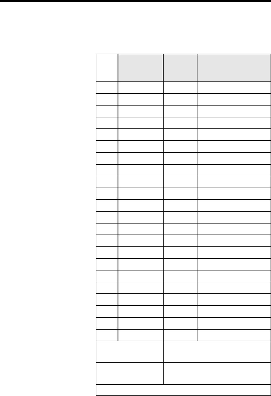
Sequencer Input Configuration for Each Add-On
Module
Location of Dispensing Stations by Component Class
Station
Class I
5.08mm (0.200")
& 10.16mm
(0.400") Pitch
Class II
5.08mm
(0.200")
Pitch*
Notes
1
9
2
9
3
99
Without Jumper Wire
3With Jumper Wire
4
9
5
99
If no Jumper Wire in Station 3
5
99
If Jumper Wire in Station 3
6
9
7
9
8
9
9
9
10
9
11
99
Any Combination
12
9
13
99
Any Combination
14
9
15
99
Any Combination
16
9
17
99
Any Combination
18
9
19
99
Any Combination
20
9
With Jumper Wire:
14 stations for Class I only
5 stations for Class I or II
1 station for Jumper Wire only
Without Jumper Wire:
13 stations for Class I only
5 stations for Class I or II
2 stations for Class I or II
*
10.16mm (0.400") pitch is not recommended.
Page 22 GS-394-02
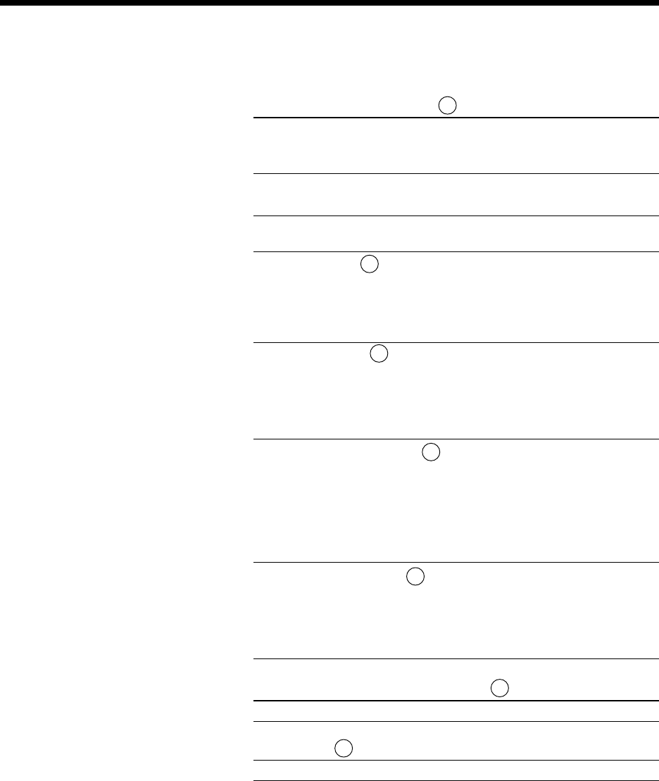
Dispensing Head Component Input Specifications
Distance Between Tapes
Class I 52.4mm ± 1.5mm (2.063" ± 0.059")
Class II 63.54mm ± 1.5mm (2.50" ± 0.059")
Wire Size and Component Sizes
Standard 5mm
Steel Wire Size
1,3
Minimum 0.38mm 0.38mm
(0.15") (0.015")
Maximum 0.81mm 0.81mm
3
(0.032") (0.032")
Copper Wire Size
1,3
Minimum 0.38mm 0.38mm
(0.15") (0.015")
Maximum 0.81mm 0.81mm
3
(0.032") (0.032")
Component Body Diameter
4
Minimum wire dia. wire dia.
Maximum 8.4mm 8.9mm
(0.330") (0.350")
Minus 2 Minus 2
times board times board
thickness thickness
Component Body Length
6
Minimum 0mm 0mm
(0") (0")
Maximum 15.75mm 15.75mm
(0.620") (0.620")
Standard Input Pitch Distances
5.08mm (0.200") or 10.16mm (0.400")
Tape Width
Standard 6.4mm (0.25")
1. Component lead diameters are for optimum performance using the listed tooling. Consult a Universal Sales Engineer for deviations
from the figures listed.
2. Increased insertion span is possible with reduction in maximum body diameter and board thickness. Consult a Universal Sales
Engineer for optional tooling.
3. When inserting components at 5mm (0.197") and 5.5mm (0.216") insertion spans, maximum lead diameter is 0.61mm (0.024").
4. At 5mm and insertion span, the maximum component body diameter is 2.29mm (0.090").
5. Minimum printed circuit board hole diameter is nominally 0.48mm ± 0.08mm (0.019" ± 0.003") + lead diameter.
6. Body length is dependent on the insertion span. See “Component Body Length Considerations” for additional information.
A
C
F
B
B
E
D

Page 23GS-394-02
Insertion Tooling Specification
1
Tooling Type
Standard 5mm
Minimum Hole Span
2
7.62 (0.300) 5.00 (0.197)
(with minimum lead
diameter)
Maximum Hole Span
2
24.13 21.59
(with maximum lead (0.950) (0.850)
diameter)
Steel Wire Lead Size Minimum 0.38 (0.015) 0.38 (0.015)
Maximum 0.81 (0.032) 0.81 (0.032)
Copper Wire Lead Size Minimum 0.38 (0.015) 0.38 (0.015)
Maximum 0.81 (0.032) 0.81 (0.032)
Component Body Minimum Wire lead dia. Wire lead dia.
Diameter
Maximum
3
10.69 (0.420) 11.68 (0.460)
minus 2 X board minus 2 X board
thickness thickness
1
Dimensions are given in millimeters; inches are in parentheses.
2
Insertion hole span is defined as the hole center distance.
3
At 5mm hole spans, maximum component body diameter is 2.29mm (0.090").
Insertion Head Input Specifications