6241f.pdf - 第42页
Page 34 GS-394-02 (See Appendix for Loader/Unloader configurations) Uncrated Air Ride Van (no skid or crating material) (skidded and plastic covering banded over machine) L X D X H 1 Weight 1, 2 L X D X H 1 Weight 1, 2 I…
Page 33GS-394-02
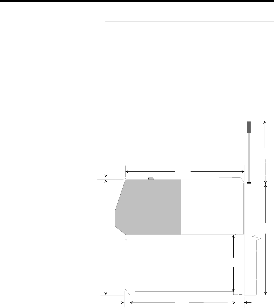
VCD/Sequencer 8 Non Pass Through
(Stand-Alone): Side View
76.2
(3)
Dimensions are in millimeters;
inch equivalents are bracketed.
133.4
(5.25)
1435.1
(56.5)
812.8
(32)
1333.5
(52.5)
Transfer
Cabinet
88.9
(3.5)
1270
(50)
88.9
(3.5)
1403.4
(55.25)
Typical
647.7
(25.5)

Page 34 GS-394-02
(See Appendix for Loader/Unloader configurations)
Uncrated Air Ride Van
(no skid or crating material) (skidded and plastic covering
banded over machine)
L X D X H
1
Weight
1, 2
L X D X H
1
Weight
1, 2
Inserter
3
1800 x 1575 x 1594 1025 2210 x 1829 x 1727 1191
(crated separately) (70.88 x 62 x 62.75) (2260) (87 x 72 x 68) (2625)
Transfer Cabinet 991 x 635 x 1321 159 1168 x 864 x 1473 209
(crated separately) (39 x 25 x 52) (350) (46 x 34 x 58) (460)
Add-On Module 1016 x 889 x 1448 218 1193 x 1067 x 1600 268
(each crated (40 x 35 x 57) (480) (47 x 42 x 63) (590)
separately)
Last Add-On Module 1346 x 889 x 1448 227 1727 x 1066 x 1600 318
(one per machine, (53 x 35 x 57) (500) (68 x 42 x 63) (700)
has chain tensioner
on end)
Air Crating Ocean Crating
(partial wood crating) (full wood crating)
L X D X H
1
Weight
1,
2
L X D X H
1
Weight
1,2
Inserter
3
2235 x 1854 x 1905 1340 2235 x 1854 x 1905 1456
(crated separately) (88 x 73 x 75) (2955) (88 x 73 x 75) (3210)
Transfer Cabinet 1194 x 889 x 1676 254 1194 x 889 x 1676 272
(crated separately) (47 x 35 x 66) (560) (47 x 35 x 66) (600)
Add-On Module 1219 x 1092 x 1676 290 1219 x 1092 x 1676 300
(each crated (48 x 43 x 66) (640) (48 x 43 x 66) (660)
separately)
Last Add-On Module 1753 x 1092 x 1676 336 1753 x 1092 x 1676 390
(one per machine, (69 x 43 x 66) (740) (69 x 43 x 66) (860)
has chain tensioner
on end)
Notes:
1. Measurements and weights are in metric figures; inch and pound equivalents are
bracketed. Measurements are rounded to the nearest whole number.
2. Weight varies as a result of pallet construction and moisture content of wood.
3. The dimension, 953.5mm (37.54") measured from the floor to the top of the rotary
table, must be maintained at installation.
Floor Space A minimum clear area of one meter (39.4") around the machine
perimeter is recommended for machine operation and servicing.
Machine Dimensions & Weights
1
Page 35GS-394-02
Service Requirements (including Uninterruptible
Power Supply)
Electrical (insertion machine)
Machine is shipped with a power cord from
machine to Uninterruptible Power Supply. A
mating connector is supplied to attach the user
provided power cord to the UPS.
The UPS has an external 5mm ground stud which
must be permanently connected to earth/building
ground with a 14 AWG or 2.5mm
2
wire that is
appropriately protected from mechanical damage.
A circuit breaker is the overcurrent device for both
the machine and the UPS. The machine breaker
has a short circuit interrupting capacity of
10,000A, and the UPS breaker has a short circuit
interrupting capacity of 1000A.
The branch circuit supplying the machine must be
protected by an approved 15 amp circuit breaker
with a delay suitable for "high inrush current" or
"transformer loads."
Air Consumption A quick disconnect with a male barbed fitting for
12.7mm (0.50") ID flexible hose is shipped with
each machine.
Pneumatic connection located in the back of the
machine, 228mm (9") from the right side and
558mm (22") from the floor.
Air Quality Non-lubricated, dry air, dewpoint must be at 11°C
(20°F) below ambient temperature. Dust
contamination: particle size of 5.0 microns or
smaller. Oil contamination: Lubricant should not
exceed 0.08 ppm at 28°C (82°F).
Note:
• Without loader, for voltages other than 230 VAC, current is 1150/
(input voltage). Power factor may vary with input voltage.
• With loader, for voltages other than 230 VAC, current is 1725 /
(input voltage). Power factor may vary with input voltage.
• CFM (Cubic Feet per Minute): Volumetric flow rate at a specified
pressure. This is used to describe the air flow requirement. This is
used to determine input air line requirements.
• SCFM (Standard Cubic Feet per Minute): Cubic foot of air at 20° C
(68º F) at atmospheric pressure. This is used to describe the
average air consumption flow requirement needed to determine
compressor capacity requirements.
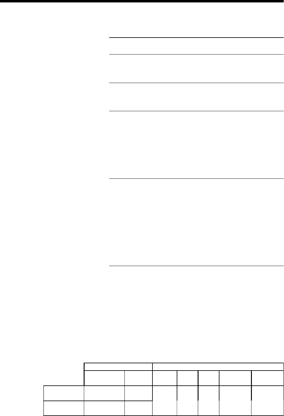
PNEUMATIC REQUIREMENTS ELECTRICAL REQUIREMENTS
Minimum Air Flow
Requirements of
Machine
Air
Consumption
of Compressor
Input
Volt ag e
Input
Frequency
Input
Breaker
Actual Power
Draw Without
Loader/Unloader
Actual Power
Draw With
Loader/Unloader
Insertion Machine
Location
85 liters per minute @
6.2 bar
3.0 CFM @ 90 PSI
7.6 SCFM 180 - 264
VAC
47 - 63Hz 15A
1150 VA
5A @ 230 VAC
1725 VA
7.5A @ 230 VAC
Additional Sequencer
Location
64 liters per minute @
6.2 bar
2.25 CFM @ 90 PSI
No Additional
Air Consumption