6241f.pdf - 第35页
Page 27 GS-394-02 Cut and Clinch Footprint 6. 15 ( 0. 24 2) 3. 61 ( 0. 14 2) 2. 11 ( 0. 08 3) 7. 98 ( 0. 31 4) 3. 58 ( 0. 14 1) 8. 13 ( 0. 32 0) 2. 72 ( 0. 10 7) 6. 10 ( 0. 24 0) 11. 51 ( 0 .4 53) 2. 62 ( 0. 10 3) Inse r…
Page 26 GS-394-02
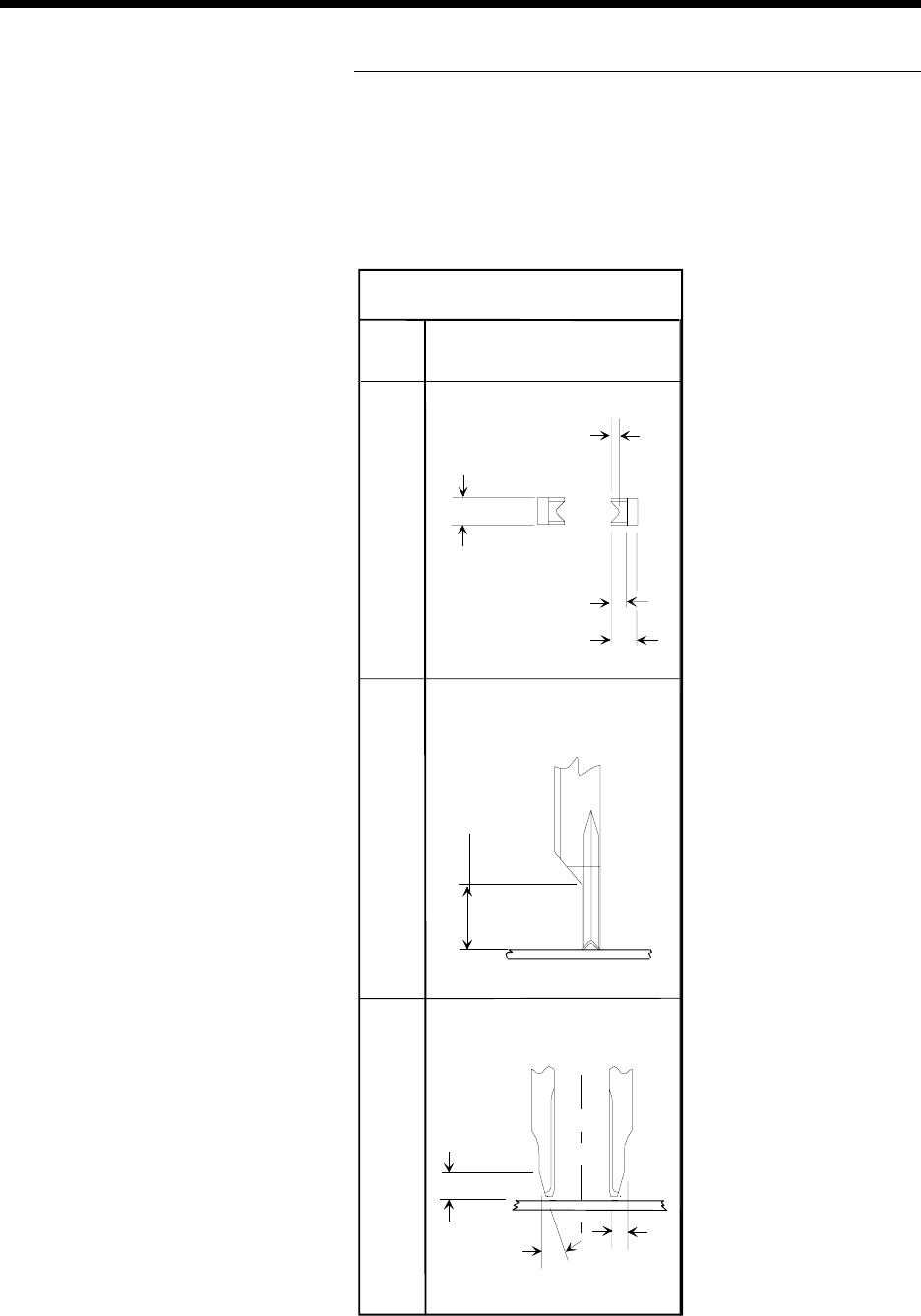
The table below provides tooling information for determining com-
ponent clearances relating to tooling footprints.
Insertion Tooling Footprint
6.43 (0.253)
Standard and 5mm
Tooling
Front View Side View Bottom View
Dimensions are in millimeters;
inch equivalents are bracketed.
0.48 (0.019)
2.29 (0.090)
1.27 (0.050)
2.29 (0.090)
3.81 (0.150)
1.27
(0.050)
15
o
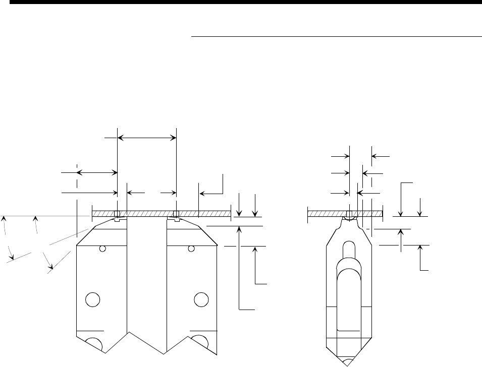
Page 27GS-394-02
Cut and Clinch Footprint
6.15 (0.242)
3.61 (0.142)
2.11 (0.083)
7.98 (0.314)
3.58 (0.141)
8.13 (0.320)
2.72 (0.107)
6.10 (0.240)
11.51 (0.453)
2.62 (0.103)
Insertion
Center Distance
45°
23°
Dimensions are in millimeters;
inch equivalents are bracketed.
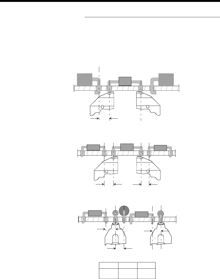
Page 28 GS-394-02
Component Clearances for Cut and
Clinch Anvil Assemblies
Side View
Axial leaded components
to previously inserted
axial leaded components.
Side View
Axial leaded components
to previously inserted
DIP components, with both
outward and inward clinch.
End View
Axial leaded components
to previously inserted
axial leaded and DIP
components shown with both
outward and inward clinch.
A B C
3.68mm 2.54mm 2.54mm
0.125" 0.100" 0.100"
A
B
C
2.54 (0.100)
2.79 (0.110)
2.54 (0.100)
Outward DIP
Inward DIP
Outward DIP
Inward DIP
Continuity Style Lead Sense
Dimensions are in millimeters;
inch equivalents are bracketed.