6241f.pdf - 第13页
Page 5 GS-394-02 Machine Status Icon Management Information Icon IM Diagnostics Icon On-Line Documentation Icon Machine Status • Current Messages — Displays current controller messages and events. Product Status — Displa…
Page 4 GS-394-02
Machine System Software
IM-Universal Platform Software (IM-UPS), and an OS/2 WARP
operating system, are standard. This graphical user interface provides
a number of capabilities, including:
System Setup
• Machine Configuration — User configuration of machine op-
tions, such as board handling and tooling.
• Event Configuration — Configuration of events for display and
control of machine status light.
• Security may be configured based on user/function.
Advanced Product Editor (APE)
• Graphical Program Generation and Editing — Component
location can be programmed/edited in either text or graphical
format. Graphically displays all component insertions relative
to PC board.
• Import of CAD Data for Program Generation (see following
section).
Product Changeover
• Load Product — User selection of previously stored product
programs.
Production Control
• Counts — Allows setting inserter counts.
• Manual Control — Manually controls (zero, move) all axes of
the machine.
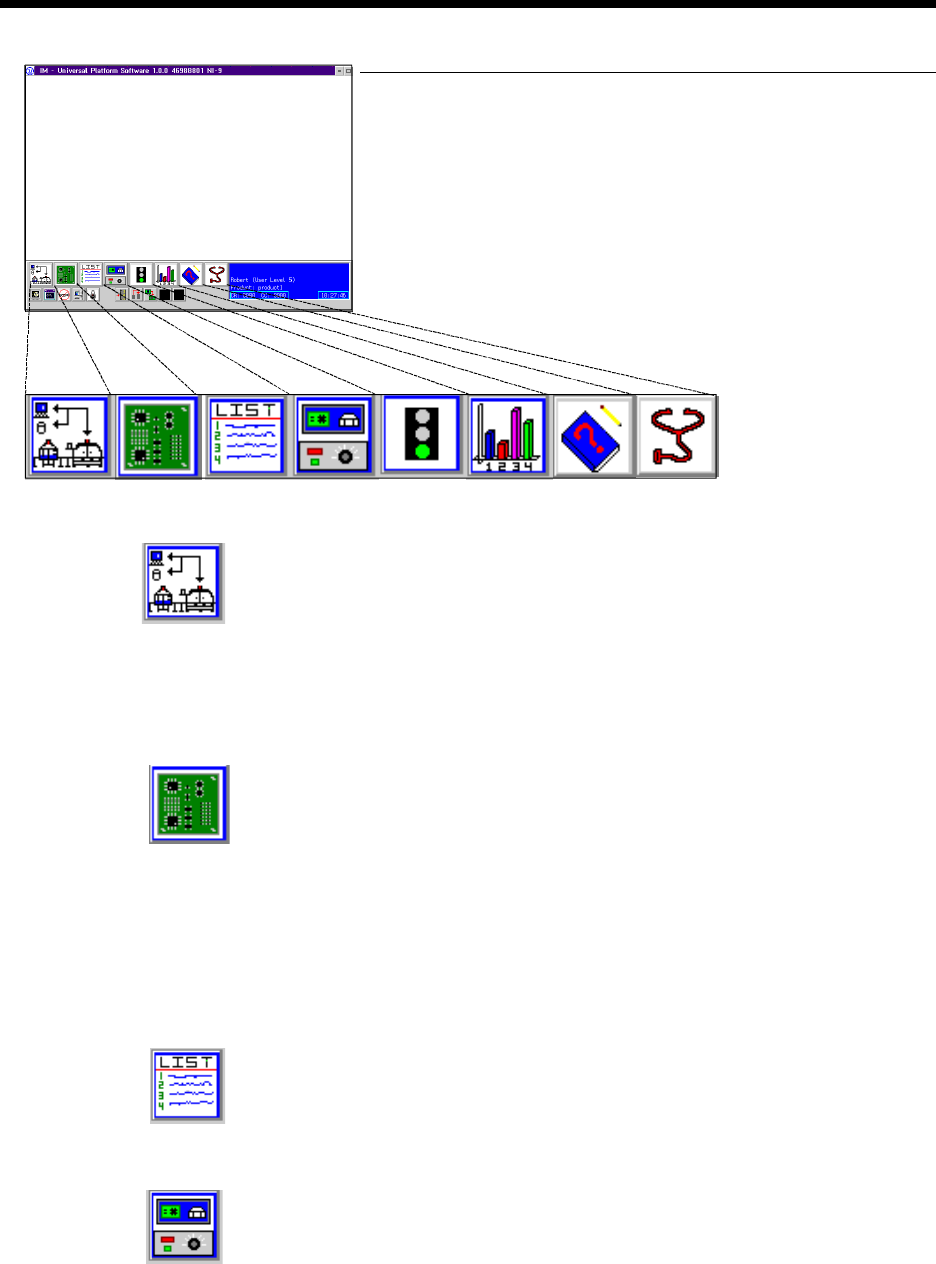
Product Changeover Icon
Production Control Icon
APE Icon
System Setup Icon
Graphical User
Interface
Page 5GS-394-02
Machine Status Icon
Management Information Icon
IM Diagnostics Icon
On-Line Documentation Icon
Machine Status
• Current Messages — Displays current controller messages and
events.
Product Status — Displays status of running product.
• Analytic Information:
• Discrete I/O — Ability to read each input and set each
output individually.
• Message History — Ability to view message log.
• Operations — Sets machine modes: Step, Single Cycle, Insert,
Pattern.
• Error Recovery — Recovery processes for operational errors,
i.e., mis-insertion.
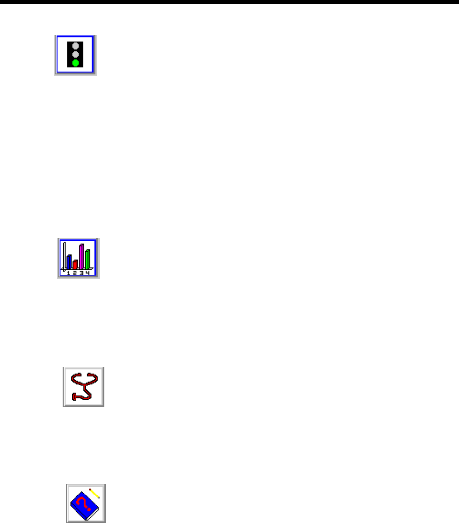
Management Information
• Timers — Collection and display of machine timers.
• Counters — Count of machine events: insertions, insert errors,
boards, Bad Board Reject, Board Error Correction, circuits.
• Component Data — Counts by component ID: placements,
errors.
From these databases, a variety of reports can be created.
IM Diagnostics
• IM Diagnostics — Ability to exercise machine sub-systems on
an individual or combined basis outside of machine control
software.
• B.E.C. Set-Up/Analysis.
• Machine Set-Up Support.
On-Line Documentation
• IM-UPS documentation is available on-line.
Page 6 GS-394-02
BOM-CAD Link: A user-defined alphanumeric string
which links a line of data in the CAD file to a component ID
in the Bill of Material (BOM) file.
Ignore: If the CAD file contains data that does not fit any of
the fields, IM-UPS may be configured to ignore this data.
A sample CAD file format is given with a brief explanation.
This file format is provided for reference only and is an ex-
ample of a typical CAD output.
CAD Data Requirements
ASCII File Format — Incoming CAD files must conform to the
American National Standard Code for Information Interchange
(ASCII). In order to accommodate a wide variety of CAD file
formats, the APE uses either a generic columnar or separator
data translation technique. All data contained in the CAD file
is identified by a position in a definition created by the user.
CAD File Requirements
X Coordinate: The X centroid coordinate location on the
board.
Y Coordinate: The Y centroid coordinate location of the
component insertion.
Theta: The rotation of the component on the board.
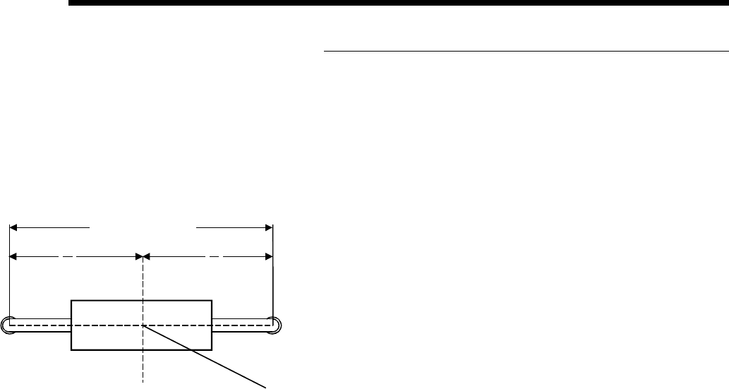
Insertion Lead Span: The distance between the centerlines
of the component leads.
Reference ID: The name assigned to the component makes
it unique to all other components in the product.
Component ID: The name of the component as it is found in
the component database.
Alias ID: The name of a component in the database to which
this component is aliased (optional).
Centroid (Top View)
Length = "L"
L
2
L
2
X, Y