Maintenance Schedule保养计划.pdf - 第13页
Page 22 Vision XP+ V AC / XP + / XP / XS 2 Mainte nance 2.5 Co oling T ract Service Instructions V ersion 1.3 2.5 Cooling T ract 2.5.1 Cleaning the Cooling zone (passive area) Fig. 2-14 Cover for Suct i on Chamber Fig. 2…
Vision XP+ VAC / XP+ / XP / XS Page 21
2 Maintenance
2.4 Process Chamber
Service Instructions
Version 1.3
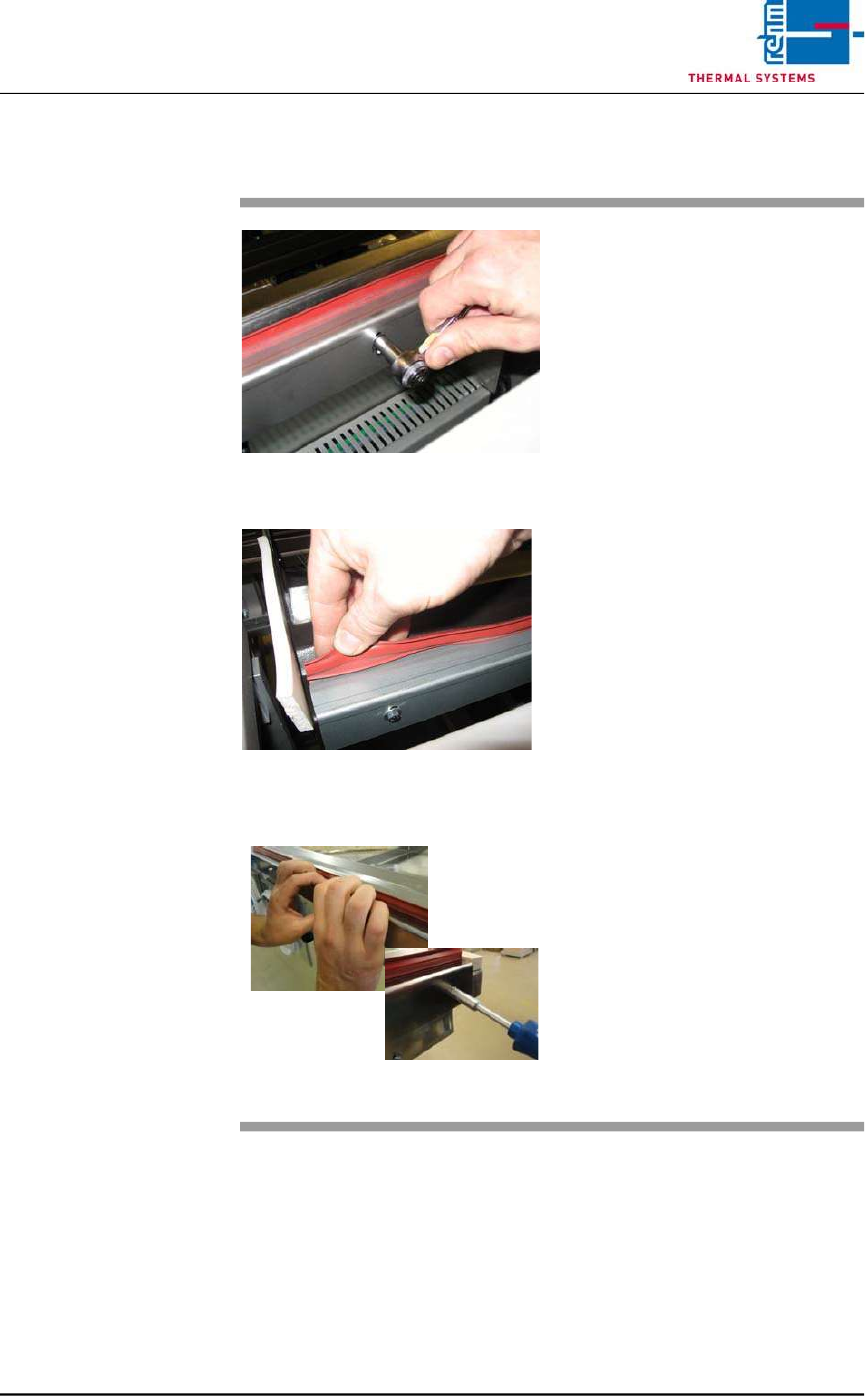
2.4.7 Replacing the Seals
Fig. 2-11 Replacing the Process Chamber
Seals
Fig. 2-12 Replacing the Process Chamber
Seals
Fig. 2-13 Replacing the Process Chamber
Seals
Consumable materials:
detergent water
Procedure:
1. The seal can be pulled by hand
from the metal bracket.
2. Then clean the metal bracket
inside with detergent water.
3. Loosen the screws slightly
4. Now, the seal can be pressed
again into the metal bracket.
5. Press down the holder sheet
with the hand and tighten the
screws again.
Page 22 Vision XP+ VAC / XP+ / XP / XS
2 Maintenance
2.5 Cooling Tract
Service Instructions
Version 1.3
2.5 Cooling Tract
2.5.1 Cleaning the Cooling zone (passive area)
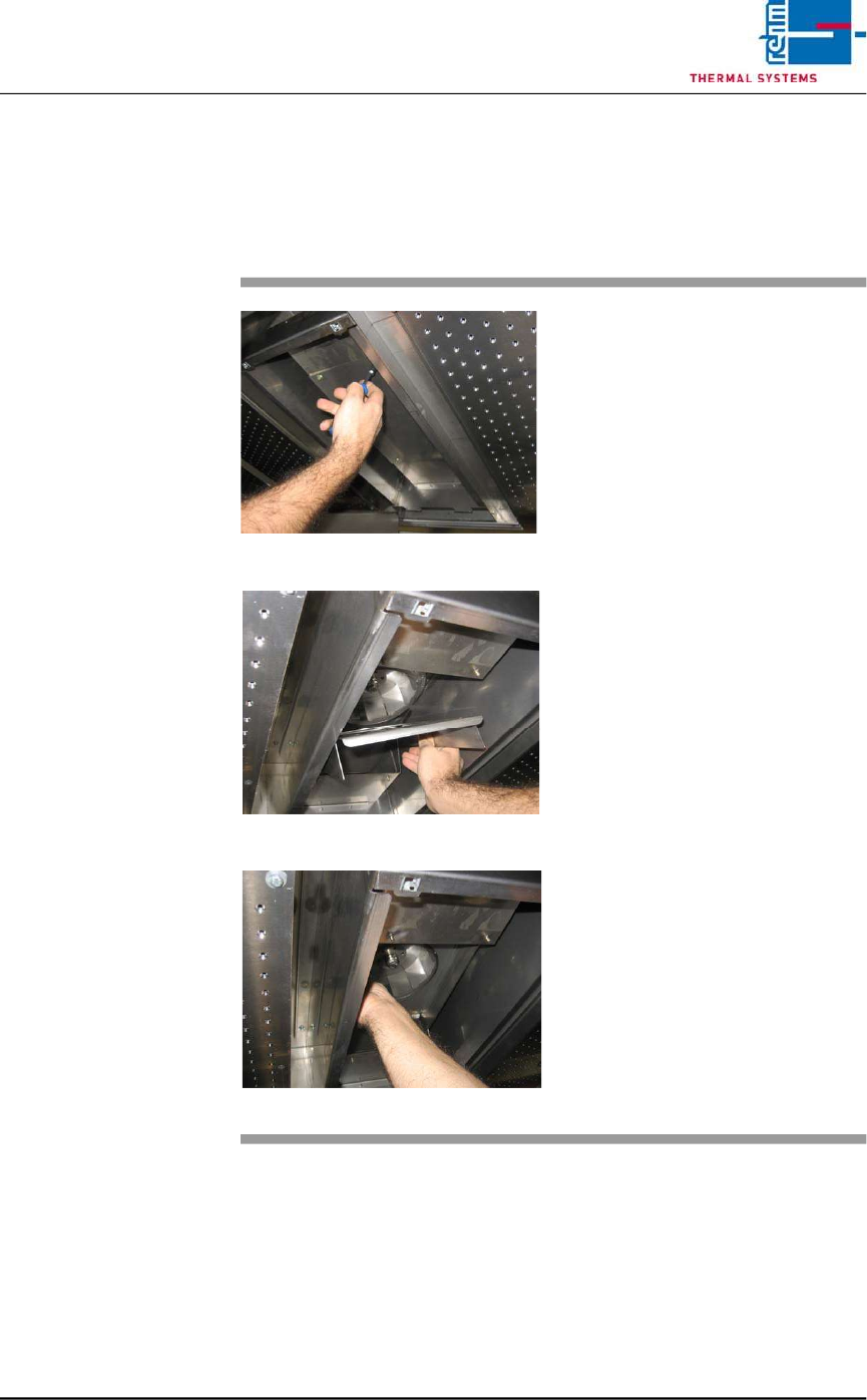
Fig. 2-14 Cover for Suction Chamber
Fig. 2-15 Sheet Metal Cover on Impeller
Fig. 2-16 Fan Impeller
The cooling zone can be dismantled
as described below. The individual
parts (e.g. nozzle field etc.) are
cleaned in a rinsing bath, or with
oven cleaner and rags.
Consumable materials, tools:
• Oven cleaner CF 1
• Rags
• Or rinsing bath
Procedure:
1. Loosen the screws on the
nozzle sheet and lift it out.
2. Unscrew suction chamber
cover (see Fig. 2-14).
3. Remove the sheet metal cover
from the impeller (see Fig. 2-
15).
4. The fan impeller is now
exposed and can be inspected,
and cleaned with oven cleaner
and rags (see Fig. 2-16).
Vision XP+ VAC / XP+ / XP / XS Page 23
2 Maintenance
2.5 Cooling Tract
Service Instructions
Version 1.3
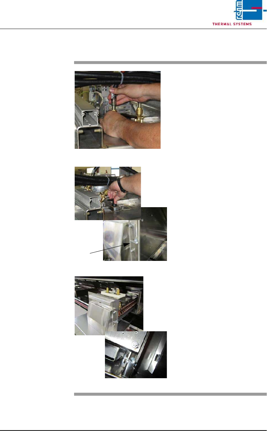
2.5.2 Cleaning the Cooler Cartridge VXS
Fig. 2-17 Removing the Water Hoses
Fig. 2-18 Folding Down the Cooler Cartridge
Fig. 2-19 Pulling the Cooler Cartridge Out
Consumable materials, tools:
• Oven cleaner
• Rags
• Rinsing bath
Procedure:
1. Remove the water hoses (see
Fig. 2-17).
2. Turn the lever above the cooler
cartridge 180° (see Fig. 2-18).
3. The cooler cartridge is folded
down. Now, turn the wing screw
by 90° to the right.
4. Raise the process chamber as
far as it will go.
5. Set the support box onto the
system frame in order to protect
the system’s paint finish. Re-
move transport safety screws
M6 at the back at the nozzle
field. (see Fig. 2-19).
6. Remove the safety splint-pin at
the cooler cartridge.
7. Pull out the cooler cartridge and
set it into the rinsing bath.
8. The insertion case for the cool-
er cartridge can be lifted out for
easier cleaning.
9. Reinstall the clean cooler
cartridge.
10. Check the water flow rate at the
flow meter