Maintenance Schedule保养计划.pdf - 第15页
Page 24 Vision XP+ V AC / XP + / XP / XS 2 Mainte nance 2.5 Co oling T ract Service Instructions V ersion 1.3 2.5.3 Additional cl eaning chute VXP+ Fig. 2-20 Additional cleaning chute Fig. 2-21 Additional cleaning chute …
Vision XP+ VAC / XP+ / XP / XS Page 23
2 Maintenance
2.5 Cooling Tract
Service Instructions
Version 1.3
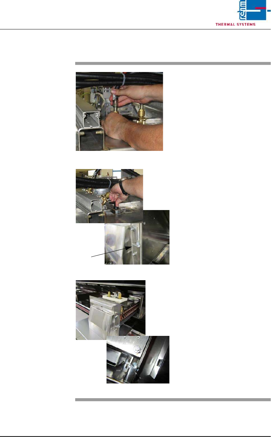
2.5.2 Cleaning the Cooler Cartridge VXS
Fig. 2-17 Removing the Water Hoses
Fig. 2-18 Folding Down the Cooler Cartridge
Fig. 2-19 Pulling the Cooler Cartridge Out
Consumable materials, tools:
• Oven cleaner
• Rags
• Rinsing bath
Procedure:
1. Remove the water hoses (see
Fig. 2-17).
2. Turn the lever above the cooler
cartridge 180° (see Fig. 2-18).
3. The cooler cartridge is folded
down. Now, turn the wing screw
by 90° to the right.
4. Raise the process chamber as
far as it will go.
5. Set the support box onto the
system frame in order to protect
the system’s paint finish. Re-
move transport safety screws
M6 at the back at the nozzle
field. (see Fig. 2-19).
6. Remove the safety splint-pin at
the cooler cartridge.
7. Pull out the cooler cartridge and
set it into the rinsing bath.
8. The insertion case for the cool-
er cartridge can be lifted out for
easier cleaning.
9. Reinstall the clean cooler
cartridge.
10. Check the water flow rate at the
flow meter
Page 24 Vision XP+ VAC / XP+ / XP / XS
2 Maintenance
2.5 Cooling Tract
Service Instructions
Version 1.3
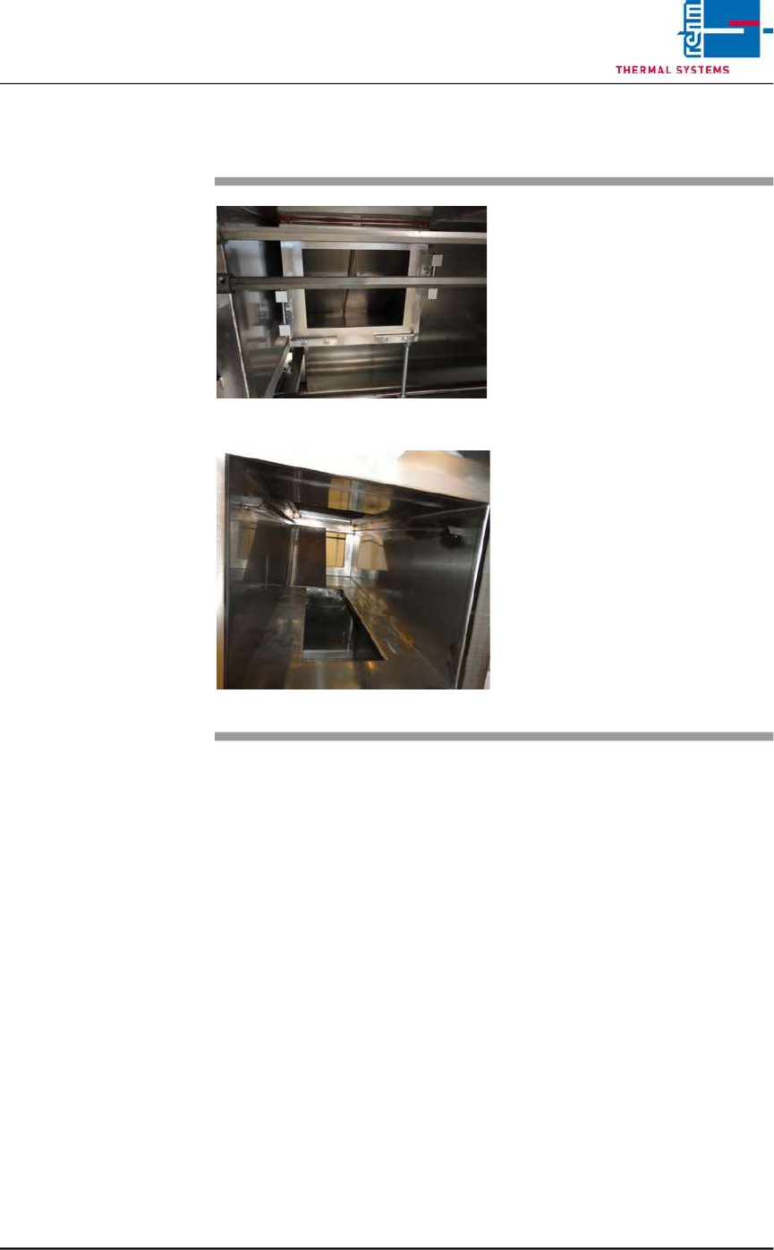
2.5.3 Additional cleaning chute VXP+
Fig. 2-20 Additional cleaning chute
Fig. 2-21 Additional cleaning chute 1
Consumables:
• Oven cleaner
• Cleaning rags
• Cleaning bath
An additional cleaning chute for the
cooling section is fitted at the front of
the plant.
This chute simplifies cleaning of the
cooling chute; the partitioning plates
may be individually removed and
placed in a suitable cleaning bath.
The cooling chute may now be
cleaned on both sides.
Thereafter reassemble everything
in reverse order.
Vision XP+ VAC / XP+ / XP / XS Page 25
2 Maintenance
2.5 Cooling Tract
Service Instructions
Version 1.3
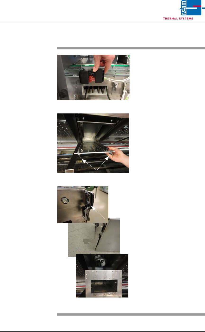
2.5.4 Clean cooling module 1 VXP+
Fig. 2-22 Disconnect power supply
Fig. 2-23 Lower nozzle field
Fig. 2-24 Unlatch, remove the cooling modu-
le
Consumables, tools:
• Oven cleaner
• Cleaning rags
• Cleaning bath
Procedure:
1. First disconnect the electric
heater supply at the back of
the plant. Then pull out the
heater at the back.
2. Now remove cooling module 1
at the front of the machine for
cleaning, as follows.
3. Rotate the wing screws on the
right and left of the nozzle field
by 90° and lower the nozzle
field for cleaning.
4. Unlatch the cooler cassette,
lift and pull out towards the
front.
5. Place the cooler cassette in the
cleaning bath.
6. Re-fit the cleaned cooler cas-
sette.
7. Check the water through-flow at
the flow meter.
8. Push the heater at the back of
the machine back in and plug in
the power supply.