Maintenance Schedule保养计划.pdf - 第24页
Vision XP+ V AC / XP+ / XP / XS Page 33 2 Mainte nance 2.9 Co ndensate T rap Service Instructions V ersion 1.3 2.9 Condensa te T rap 2.9.1 Cleaning of Condens ate T r ap VXP (option) Fig. 2-42 Condensa te T rap Fig. 2-43…
Page 32 Vision XP+ VAC / XP+ / XP / XS
2 Maintenance
2.8 Water Tank - Checking and Refilling the Water Fill-
Level (Option)
Service Instructions
Version 1.3
2.8 Water Tank - Checking and Refilling the Water Fill-Level
(Option)
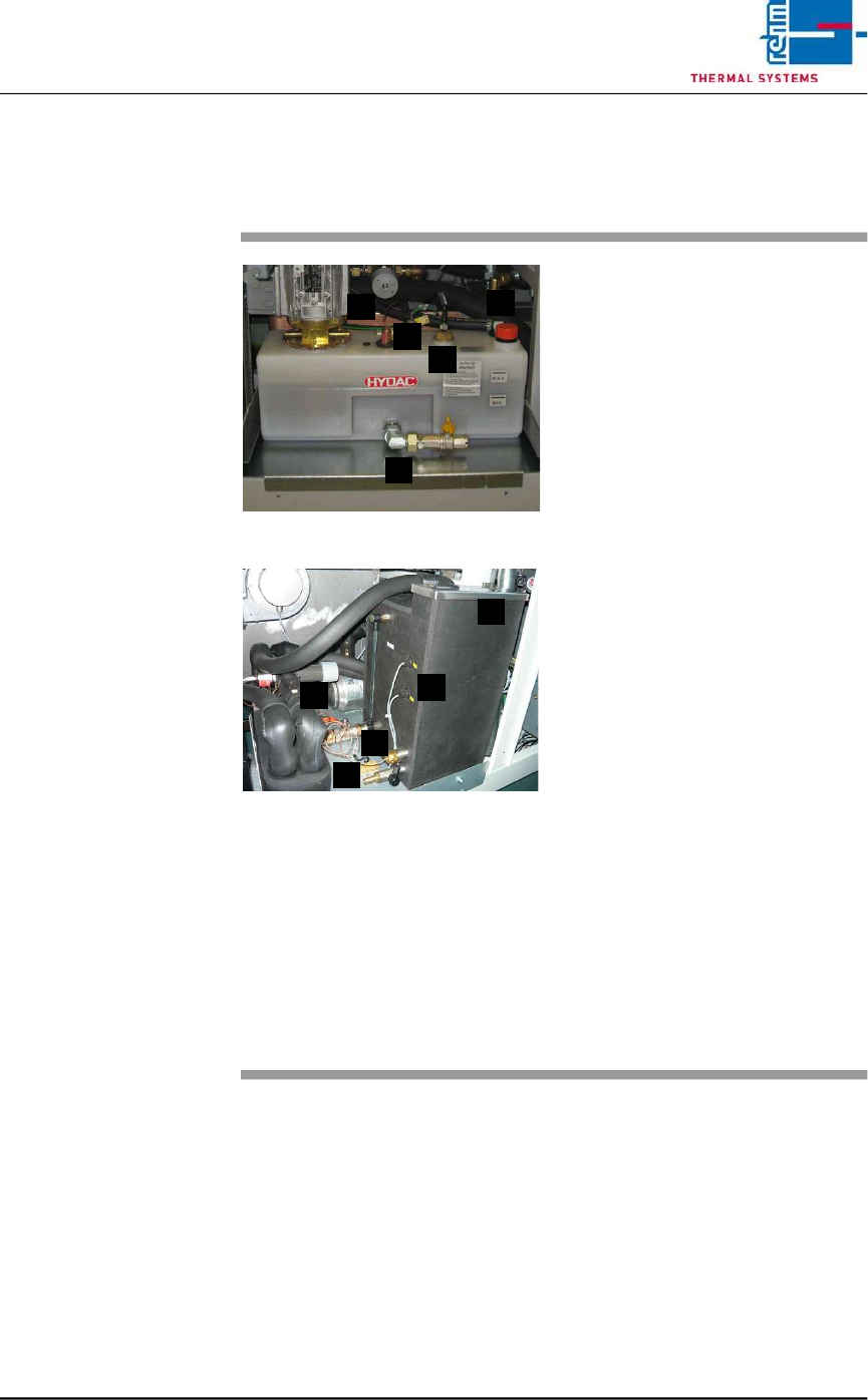
Fig. 2-40 Checking the Water Fill-Level
Fig. 2-41 Checking the Water Fill-Level, CN
The water tank is located behind the
second door from the right.
Consumable materials, tools:
• Water
• Antifreeze
Note!
Coolant is mixed using 1 part
antifreeze to 3 parts water.
• Watering can or similar container
Procedure:
1. The front of the water tank is
marked with the designations
MAX. and MIN.
2. When the fill-level drops to the
minimum mark, the tank must
be refilled with coolant to the
maximum mark.
3. For re-filling open the filling port
(D) at the tank and fill in the
mixed cooling liquid.
Cooling system components:
A) Cooling water controller
B) Water leak and minimum water
level sensor
C) Connection for draining water
D) Filling port
E) Temperature watchdogs
A
B
C
D
E
A
C
E
B
D
Vision XP+ VAC / XP+ / XP / XS Page 33
2 Maintenance
2.9 Condensate Trap
Service Instructions
Version 1.3
2.9 Condensate Trap
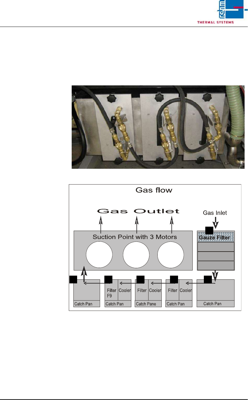
2.9.1 Cleaning of Condensate Trap VXP (option)
Fig. 2-42 Condensate Trap
Fig. 2-43 Condensate Trap Layout
Make sure that the following conditions have been fulfilled before working on
the condensate trap:
• Make sure that the fans are switched off and that water pressure has been
relieved with the help of the software. The “Cooling Tract Stopped”
message must appear at the monitor screen and the lock must be opened.
Refer to the “Main Window” subsection of the “Software” chapter in the
operating instructions to this end.
• Undo the water connections.
A
D C C BB
Page 34 Vision XP+ VAC / XP+ / XP / XS
2 Maintenance
2.9 Condensate Trap
Service Instructions
Version 1.3
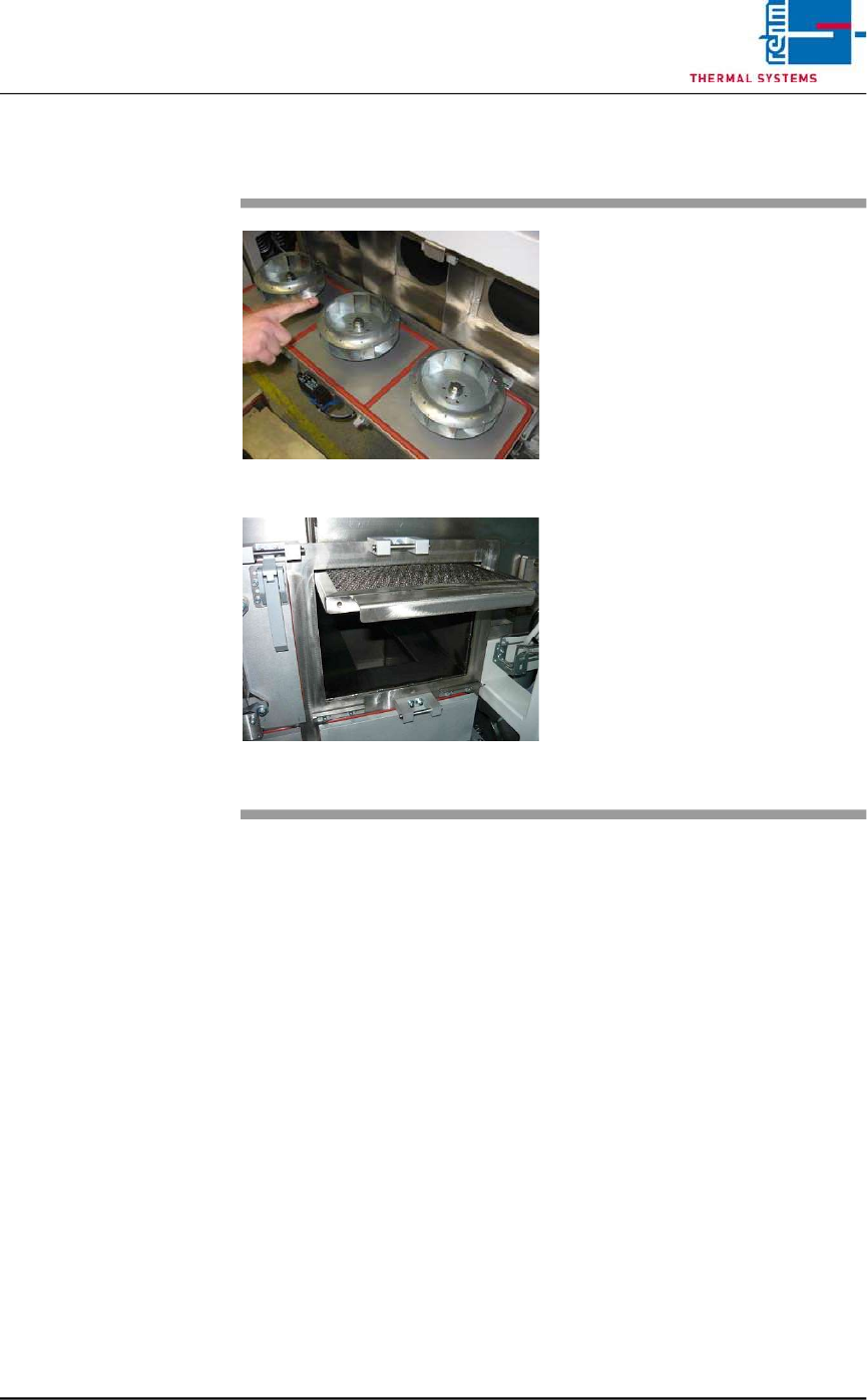
2.9.2 Clean the suction ducts and the Gauze Filter (A)
Fig. 2-44 Pulling Out the Gauze Filter
Fig. 2-45 Pulling out of the Gauze Filter
Wipe out the suction ducts behind
the fan wheels with the oven
cleaner.
The Gauze Filter are located in the
suction duct on the right side of the
Condensation Trap (see Fig. 2-22,
point A).
Consumable materials, tools:
• Oven cleaner
• Rags
• Rinsing bath
Procedure:
1. Pull the gauze filter out and set
it into a rinsing bath.
2. Clean the opening for the gauze
filter next to the condensate
trap with oven cleaner and rags.
3. Reinsert the cleaned gauze
filter.