Maintenance Schedule保养计划.pdf - 第28页
Vision XP+ V AC / XP+ / XP / XS Page 37 2 Mainte nance 2.9 Co ndensate T rap Service Instructions V ersion 1.3 2.9.5 Cleaning Work at the Cooler Units (D) Fig. 2-50 Pulling Out the Cooler Unit Fig. 2-51 Pulling Out the F…
Page 36 Vision XP+ VAC / XP+ / XP / XS
2 Maintenance
2.9 Condensate Trap
Service Instructions
Version 1.3
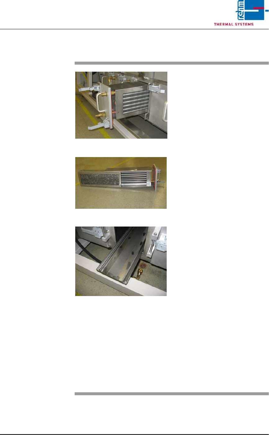
2.9.4 Cleaning Work at the Cooler Units (C)
Fig. 2-47 Pulling Out the Cooler Unit
Fig. 2-48 Pulling Out the Filter
Fig. 2-49 catch pan
The cooler units are located in the
bottom row of the condensate trap
(see item C in Fig. 2-47).
Consumable materials, tools:
• Oven cleaner
• Rags
• Rinsing bath
Procedure:
1. Open both locking levers and
pull out the cooler unit (see Fig.
2-48).
2. Pull the filter out of the cooler
unit and set it into the rinsing
bath.
3. Lift the cooler out of the cooler
unit and set it into the rinsing
bath as well.
4. Pull out the catch pan, empty it
an set it into the rinsing bath.
Caution!
The seals must protrude from
the bath. Otherwise they will be
damaged.
5. Clean the seals with industrial
alcohol and rags.
6. Clean the opening for the cooler
unit at the condensate trap with
oven cleaner and rags.
7. Reassemble cleaned parts and
insert them into the condensate
trap.
Note!
The quick couplings should be
lubricated occasionally, using
suitable lubricant, thereafter audibly
click the couplings back in.
Vision XP+ VAC / XP+ / XP / XS Page 37
2 Maintenance
2.9 Condensate Trap
Service Instructions
Version 1.3
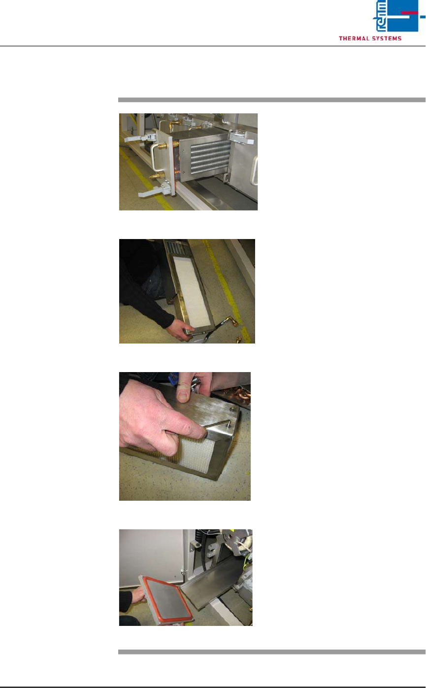
2.9.5 Cleaning Work at the Cooler Units (D)
Fig. 2-50 Pulling Out the Cooler Unit
Fig. 2-51 Pulling Out the Filter unit F9
Fig. 2-52 Metal Frame
Fig. 2-53 Drip pan
The cooler units are located in the
bottom row of the condensate trap.
Consumable materials, tools:
• Oven cleaner
• Rags
• Rinsing bath
• Allen wrench 2,5 mm
Procedure:
1. Open both locking levers and
pull out the cooler unit.
2. Pull the filter (F9) out of the
cooler unit.
3. Lift the cooler out of the cooler
unit and set it into the rinsing
bath as well
4. Open the metal frame of the
filter (F9) with a 2,5 mm allen
wrench and replace the paper
filter (one-way).
Caution!
The seals must protrude from
the bath. Otherwise they will be
damaged.
5. Clean the seals with industrial
alcohol and rags.
6. Pull out the catch pan, empty it
an set it into the rinsing bath.
7. Clean the opening for the cooler
unit at the condensate trap with
oven cleaner and rags.
8. Reassemble cleaned parts and
insert them into the condensate
trap.
9. All connections restore.
Page 38 Vision XP+ VAC / XP+ / XP / XS
2 Maintenance
2.9 Condensate Trap
Service Instructions
Version 1.3
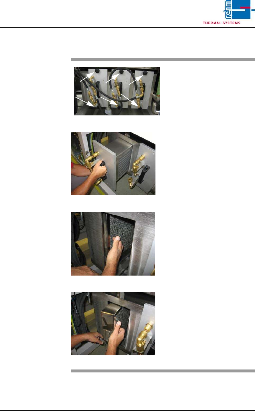
2.9.6 Cleaning of Condensate Trap VXS (Option)
Fig. 2-54 Condensate trap
Fig. 2-55 Condensate trap 1
Fig. 2-56 Condensate trap 2
Fig. 2-57 Condensate trap 3
The condensate trap is installed in
the back of the machine.
Consumable materials:
• Cleaning agent
• Cleaning cloth
Procedure:
1. Open the casing doors at the
back of the machine.
2. Now disconnect the quick con-
nectors from the cooling unit.
3. Loose the knurled screws to
pull out the cooling units. Now
put the units in a cleaning bath.
4. Also, pull out the gauze filter
from the condensate trap and
put it in a cleaning bath.
– Clean up all contaminated
surfaces with a cleaning
cloth and a suitable clean-
ing agent.
– Put the cleaned cooling unit
and filter back to the con-
densate trap.
– After the cleaning proce-
dure put all items together
again in reverse order.
– Fix the knurled screws and
connect the flexible hoses
again in correct order - see
picture above.
Note!
The quick couplings should be lubri-
cated occasionally, using suitable
lubricant, thereafter audibly click the
couplings back in.