TS577R-UserGuide.pdf - 第9页
9 5.2 Setup for Auger Valve without Encoder Motor 5.2.1 Seclect Controlling Mode The TS570R can be used as a stand-alone controller or can be integrated to any robotic systems. A. To use as stand-alone controller: Go to …
8
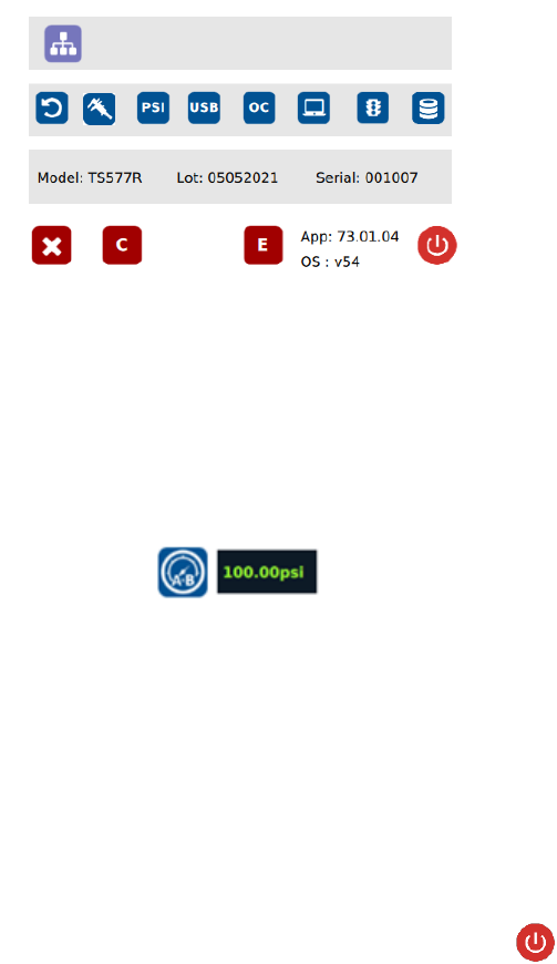
3. Turn pressure adjustment knob counterclockwise until the wheel can no
longer be turned.
4. Touch the 0 icon to set the pressure to 0
5. Turn pressure adjustment knob clockwise until display output pressure is
100 psi
6. Touch the 100 icon to set the pressure to 100
Warning: Do not turn knob all the way clockwise. 100 psi upper bound should
be set as soon as display output pressure goes from 99 to 100 psi. Continuing
to turn knob clockwise despite pressure on display already being set at
100psi will result in incorrect output pressure readings if the 100 icon were to
be pressed at that time.
Note: The digital values shown at “0” and “100” icons are for reference only.
The actual calibrated values will be different
7. Touch the Reboot icon to save the settings and reboot the system
8. Wait until the system completes the rebooting sequence and the home
screen is displayed
The unit’s pneumatic system is now calibrated and ready to operate
9
5.2 Setup for Auger Valve without Encoder Motor
5.2.1 Seclect Controlling Mode
The TS570R can be used as a stand-alone controller or can be integrated to
any robotic systems.
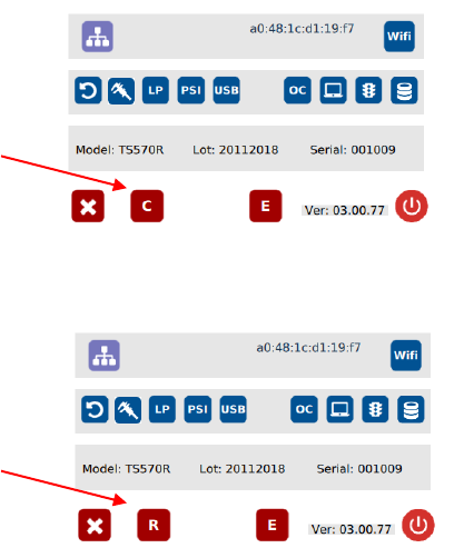
A. To use as stand-alone controller:
Go to setup screen to check for controlling mode. If the icon “C” is showing,
then it is already set as stand-alone controlling mode. If the icon “R” is
showing, press this icon to change to “C”
B. To use as integrated controller to robot/automation:
Press icon “C” to change to “R”
]
Stand-alone controlling
mode
Robot mode (integrate
to robotic system)
10
5.2.2 Voltage Input Adjustment
Note: Input voltage controls the motor speed (RPM). Higher input voltage
will increase motor speed and vice versa lower input voltage will decrease
motor speed. Recommended input voltage range is 5-24VDC.
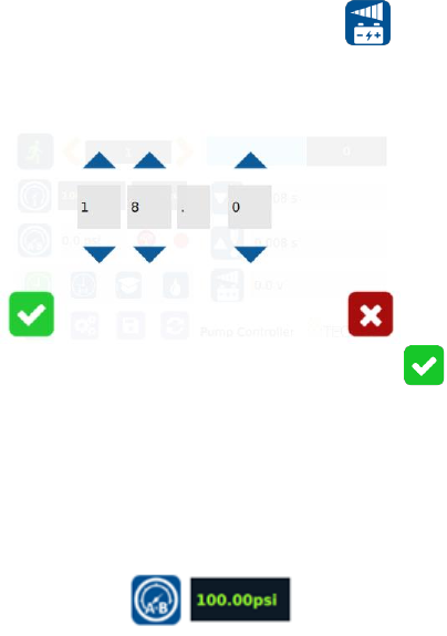
1. Touch the Input Voltage Icon to enter the setup screen
2. Touch the Up and Down arrows to set the desired input voltage. Maximum
input voltage is 24VDC.
3. Touch the Check Mark icon to save and exit
5.2.3 Pressure Adjustment
Note: Pressure on port A is a contanst pressure.
Pressure on port B is synchronized with the motor signal. It only turns on
when the dispense cycle is activated.
1. Output pressure on Port A and B wil be displayed in the following window:
Pressure to port A.B can be adjusted from 0 to 100 psi by rotating the
pressure adjustment knob.
2. Rotate the adjustment knob in the counterclockwise direction to descrease
output pressure.
3. Rotate the adjustment knob in the clockwise direction to increase output
pressure.
Note: To ensure output pressure to A.B matches manual pressure
adjustments, please make sure pressure calibration Section 5.1.2 has been
completed.