M4serviceManual_e.pdf - 第34页
3 Mechanical Section 3-4 ACTION: Removal of the lower head cover ① Remove the four pl astic screws fixing the lower head cover. ② Pull out the lower head cov er toward the front to remove it from the head base. Lower hea…
3 Mechanical Section
3-3
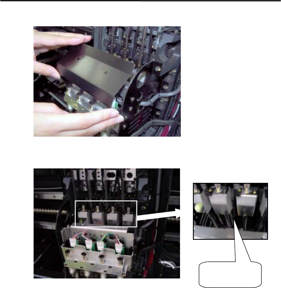
③Remove the upper head cover.
④When the upper head cover is removed, Z axis ball screw/ linear guide will be appeared.
Z-axis ball screw/
linear guide
3 Mechanical Section
3-4
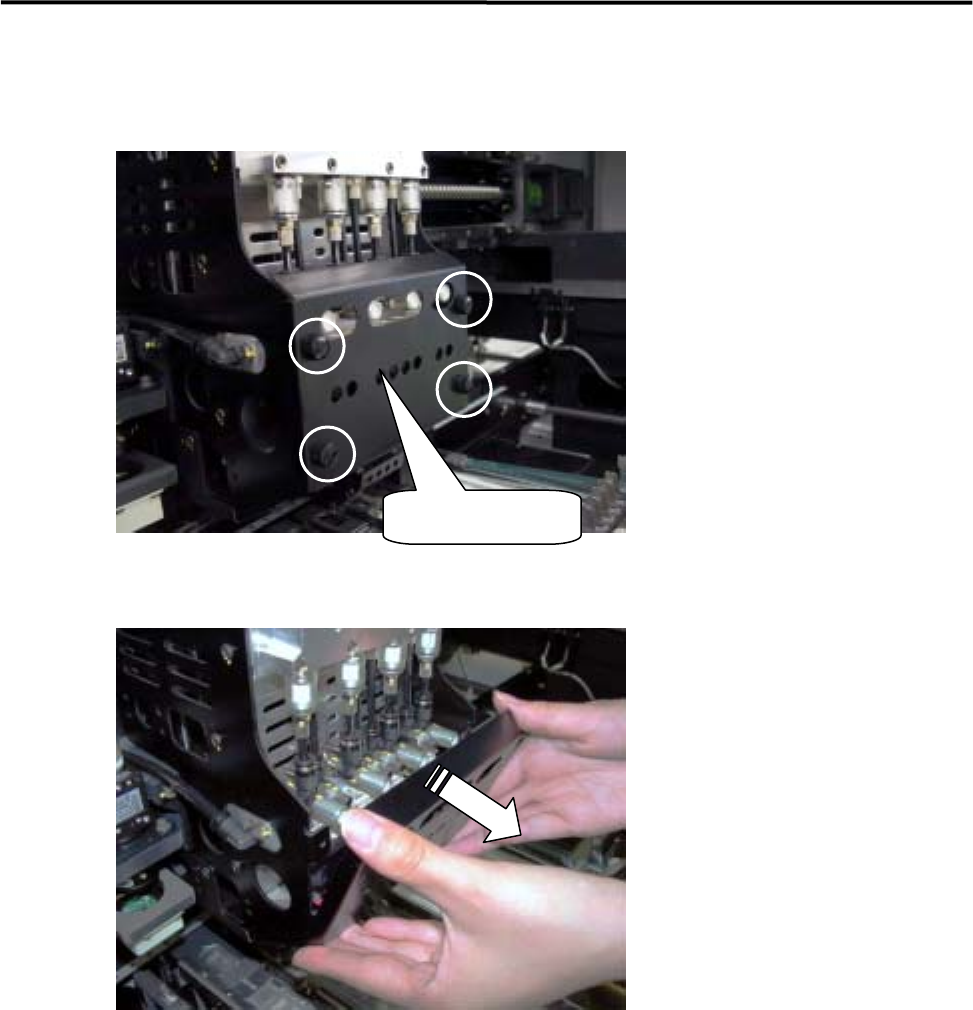
ACTION: Removal of the lower head cover
① Remove the four plastic screws fixing the lower head cover.
② Pull out the lower head cover toward the front to remove it from the head base.
Lower head cover
3 Mechanical Section
3-5
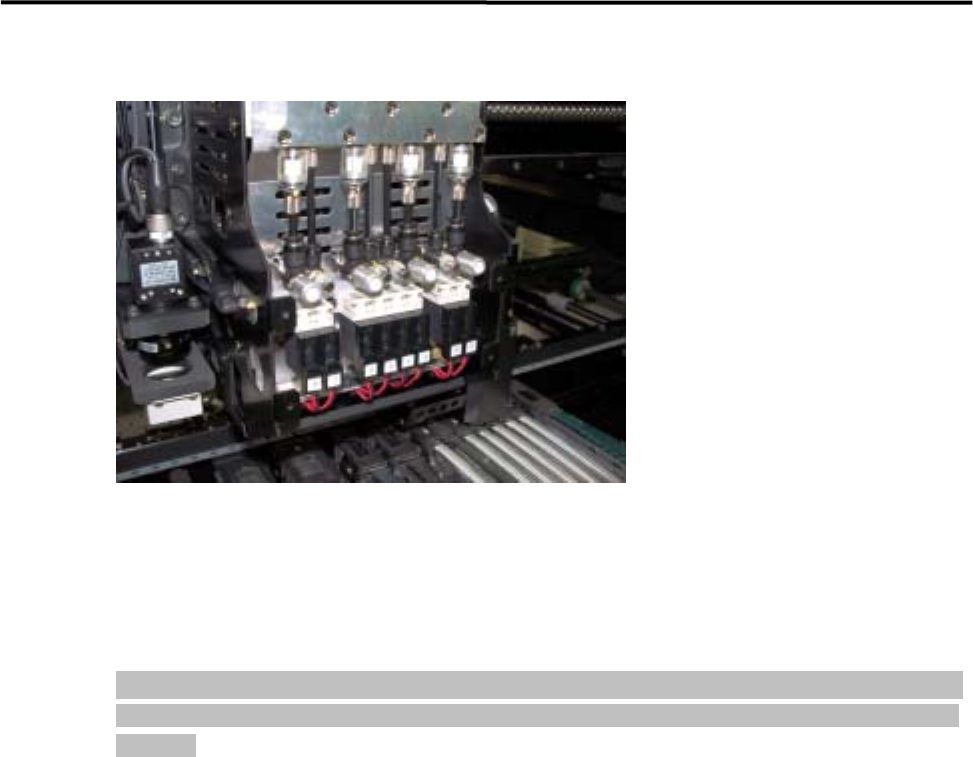
③ The head manifold section will be exposed, enabling easy inspection.
ACTION: Installation
Installation of each head cover must be carried out in reverse order of removal.
NOTE: When attaching each head cover , tighten the plastic screws firmly to fix the head cover to the head base
securely. If the head cover is not secured sufficiently, it may come off during operation, causing serious
accidents.