M4serviceManual_e.pdf - 第45页
3 Mechanical Section 3-15 Nozzle holder A ball and spring that hold t he nozzle may not perform smoothly due to the entry of dust and dirt, whi ch will cause a nozzle-dropping. Make a periodic check of the nozzle escape.…
3 Mechanical Section
3-14
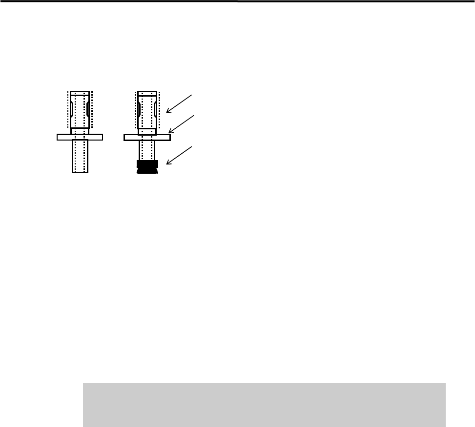
■ Applying Silicon Grease
After the nozzle is cleaned, it must be coated with silicon grease.
Apply silicon grease.
Nozzle ID sticker
Suction pad
● Nozzle outer surface
Apply a slight amount of grease to the outer surface (indicated by dotted lines in the above illustration), and
then wipe it off with a dry cloth.
NOTE: Silicon grease must be applied so that it forms a thin film on top of the surface.
● Suction pad
Application of oil content is needed to prevent deterioration of the rubber. Apply a slight amount of grease
to the outer surface of the suction pad, and then wipe it off with a dry cloth.
NOTE: Silicon grease must be applied so that it forms a thin film on top of the surface.
Do not apply excessive amounts of grease. This may cause collection of dirt
or dust in the air passage and on mounted components, resulting in
component mount failure.
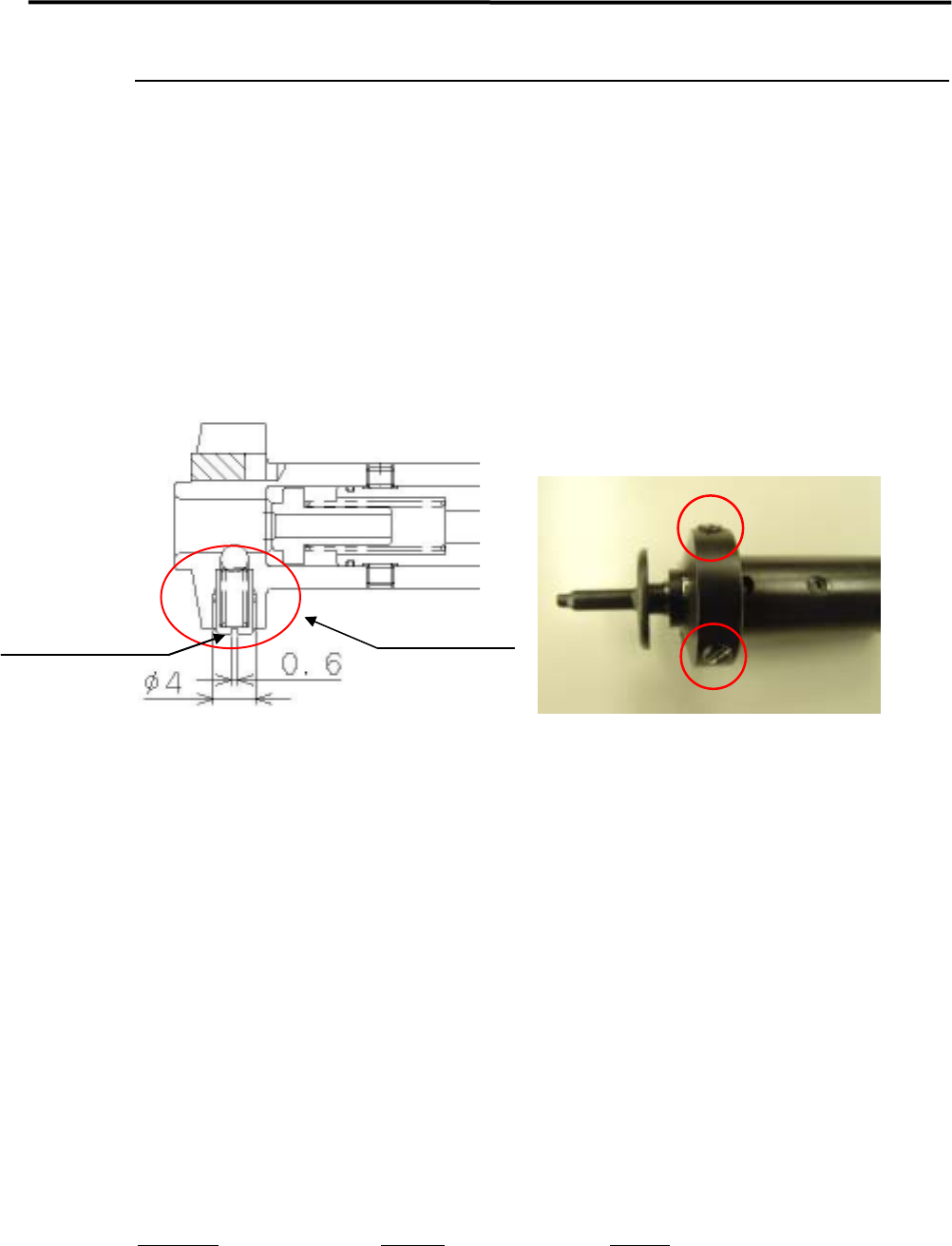
● Checking the nozzle escape
After grease is applied to the nozzle’s outer surface, attach the nozzle to the head and check the condition of
the nozzle escape.
NOTE: When the nozzle is placed in the head (nozzle holder), it can slide a few millimeters vertically. This nozzle
sliding movement is called nozzle escape.
ACTION:
① Attach the nozzle to the head.
② Push the nozzle gently with fingers up to the top dead center of the nozzle escape.
③ Release fingers gently and check that the nozzle returns to the lower dead center smoothly.
NOTE: If the nozzle escape is not smooth, there may be problems with component suction and mounting. If the
nozzle gets caught or does not move smoothly, check the nozzle holder and nozzle’s inner/outer surfaces
for collection of foreign matter or scratches.
3 Mechanical Section
3-15
Nozzle holder
A ball and spring that hold the nozzle may not perform smoothly due to the entry of dust and dirt, which
will cause a nozzle-dropping. Make a periodic check of the nozzle escape. If any *abnormal conditions are
seen, clean the nozzle holder. (*The nozzle stays up and does not go back to its initial position, or the nozzle
drops easily etc.)
NOTE: Please handle the spring and ball inside the nozzle holder carefully, since they tend to get lost. It is
recommended that spare parts should be kept handy and start removal.
Spring holder
Nozzle holding parts
ACTION:
① Remove the spring holder with a flat blade screw.
NOTE: Adhesive has been applied around the screw head to prevent loosening. When removing the spring holder
for the first time, take off the adhesive and start removal.
② Take the spring and ball out.
(When it is difficult to take the ball out, push it from inside of the nozzle holder.)
③ Remove the spring from the spring holder with tweezers.
④ Remove dust and dirt around the hole area, the spring and ball.
⑤ Apply the proper amount of Silicone Grease to the spring and ball.
Put them back in reverse order of removal. Fasten the spring holder until it touches the inner wall.
Part Name
Part No. Remark
HOLDER,SPRING LG0-M714P-00X Spring holder
SPRING,COMP. LG0-M71CC-00X Spring
STEEL,BALL LG0-M71B5-00X Ball
3 Mechanical Section
3-16
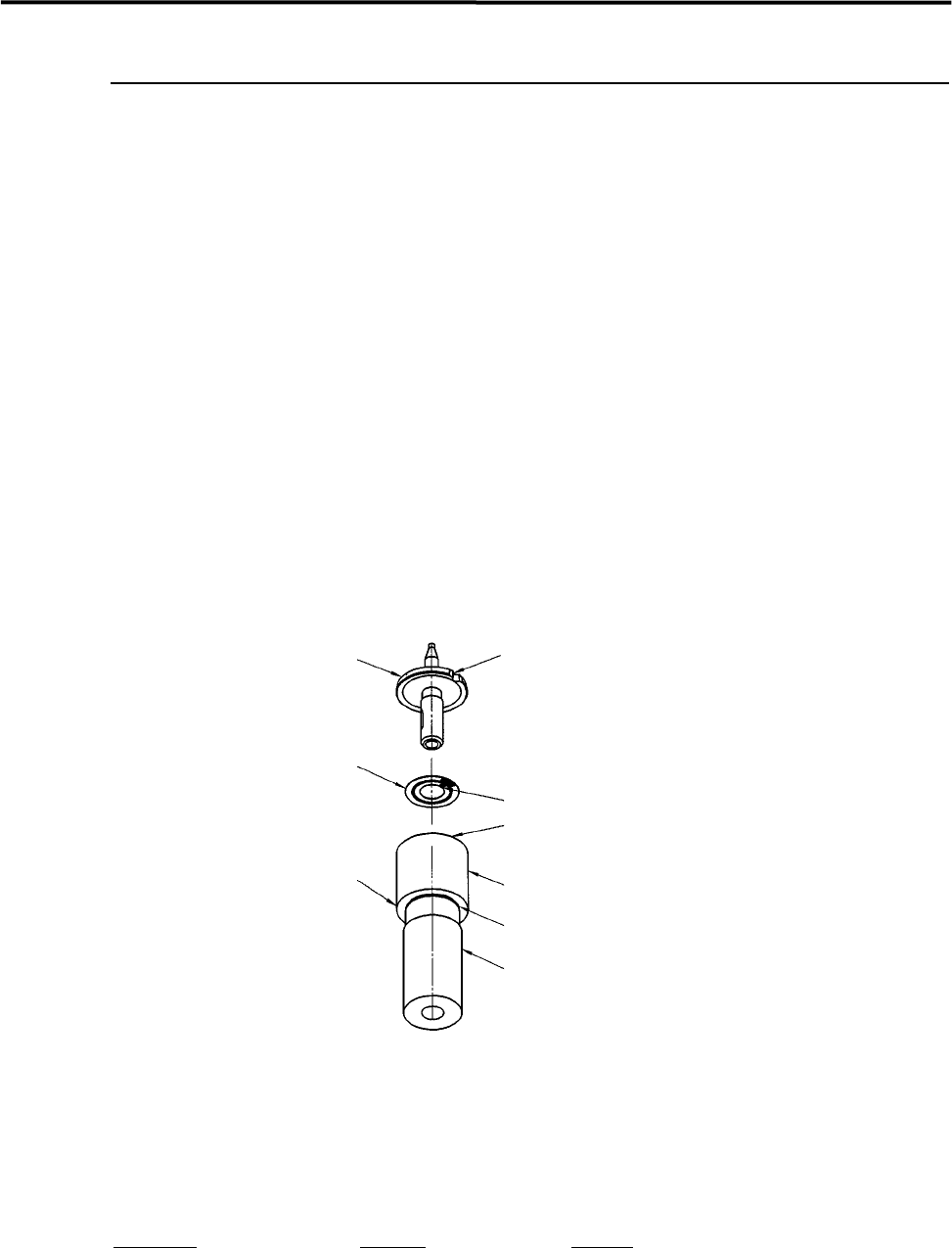
Nozzle Recognition Stickers
Labeling a Nozzle ID Sticker to a Nozzle
ACTION:
① Wipe off oil, dust, or water from the upper side of the nozzle flange with alcohol.
② Slide the ring of the labeler until the groove in the labeler shaft appears.
③ Peel off the sticker from its slip sheet using tweezers.
④ With the sticker’s adhesive side upward, align the sticker’s angle mark to the ring’s positioning mark.
Set the sticker into the ring, being careful not to touch the sticker’s adhesive side.
⑤ Make sure the sticker is properly placed in the ring.
⑥ Insert the nozzle upside down into the hollow of the labeler shaft, while aligning the nozzle cutoff to
the ring’s positioning mark.
⑦ Push up the labeler shaft so that the sticker sticks to the nozzle flange.
Nozzle
Cutoff
Nozzle ID sticker
Positioning mark
Ring
Groove
Shaft
Labeler for
nozzle ID sticker
Angle mark
NOTE: If the shaft is pulled out of the ring too much, it may come off. If it comes off, align the shaft’s slot with the
ring’s positioning pin and then insert the shaft into the ring slowly.
Part Name
Part No. Remark
ID SEAL TOOL, ASSY. LG0-M8903-00X ID sticker tool