SIPLACE D系列Servicemanual.pdf - 第31页
Service Work D1/D2 Gantry Servicemanual (internal version) SIPLACE D Series 31 4.1.2.3 Replacing the Y Linear Moto r– Secondary Part (Magnet s) [00355754-xx] Tools and Equipment Set of DIN 911 Allen keys Belt tension…
Service Work
Gantry D1/D2
30 Servicemanual (internal version) SIPLACE D Series
To move past a gantry during fixture, you will need to interrupt the procedure. Proceed as follows:
X Before starting work, you should pull the gantries as far as possible to the right.
X Extract the fixing pin from the adhesive device.
X Remove the adhesive device.
X Move the gantry to the left.
X Thread the scale back into the adhesive device.
X Continue fixing the scale.
X Press the last piece of the scale down with your hand and with the help of a tear-resistant cloth.
X You can now press the scale down again firmly, if required. To do this, slide the adhesive device over
the scale.
X Remove the centering pin.
X Clean the scale with a cloth and ethanol.
X Clean the reading surface of the incremental encoder with a cloth and ethanol or with a SIPLACE
cleaning tip.
X Fit the incremental encoder with the three fastening screws so that there is a gap of 0.4 mm between
the incremental encoder and the scale. Use a suitable thickness gauge (plastic).
X Check the track signals.
X Calibrate the machine zero point.
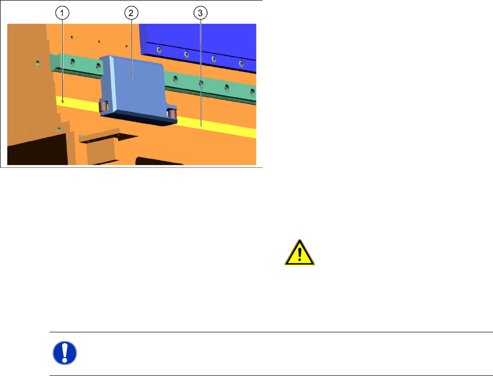
4-7: Fitting with scale - adhesive device
Legend
1. Drilling
2. Complete adhesive device
3. Scale
Start fixture at the drilling (1), on the left side of the
machine.
X Fit the scale (3) onto the centering pin and
push this into the drilling. At the same time,
place the adhesive device (2) so that the scale
is fixed horizontally onto the adhesive surface.
X Move the adhesive device to the right. While
doing so, press the scale and the adhesive
device firmly against the adhesive surface.
Carefully pull off both strips, piece by piece,
from the scale.
ATTENTION: Make sure that no
blisters or uneven areas are formed.
If this does occur, the scale must be
removed and replaced with a new
scale.
NOTE:
Fasten the scale as far as possible in one go. This prevents unnecessary interruptions to the
fixture process.
Service Work
D1/D2 Gantry
Servicemanual (internal version) SIPLACE D Series
31
4.1.2.3 Replacing the Y Linear Motor– Secondary Part (Magnets) [00355754-xx]
Tools and Equipment
Set of DIN 911 Allen keys
Belt tension measuring device TSM [00326015-xx]
"Measuring belt tensions" operating instructions
Cable ties
SITEST program
Parts
Linear motor – secondary part "long" [00355754-xx]
Linear motor – secondary part "short" [00355752-xx]
Removal
X Switch off the machine and secure it to prevent unauthorized reactivation.
X Move the relevant gantry so that you can access the required permanent magnet:
Gantry 1 D1/D2: Dismantle the left permanent magnet segment of the Y-axis.
Gantry 2 D2: Dismantle the right permanent magnet segment of the Y-axis.
X Remove the black cover strips on the crossbeam above the gantry concerned (3 M6 x 8 hexagon
socket-head screws).
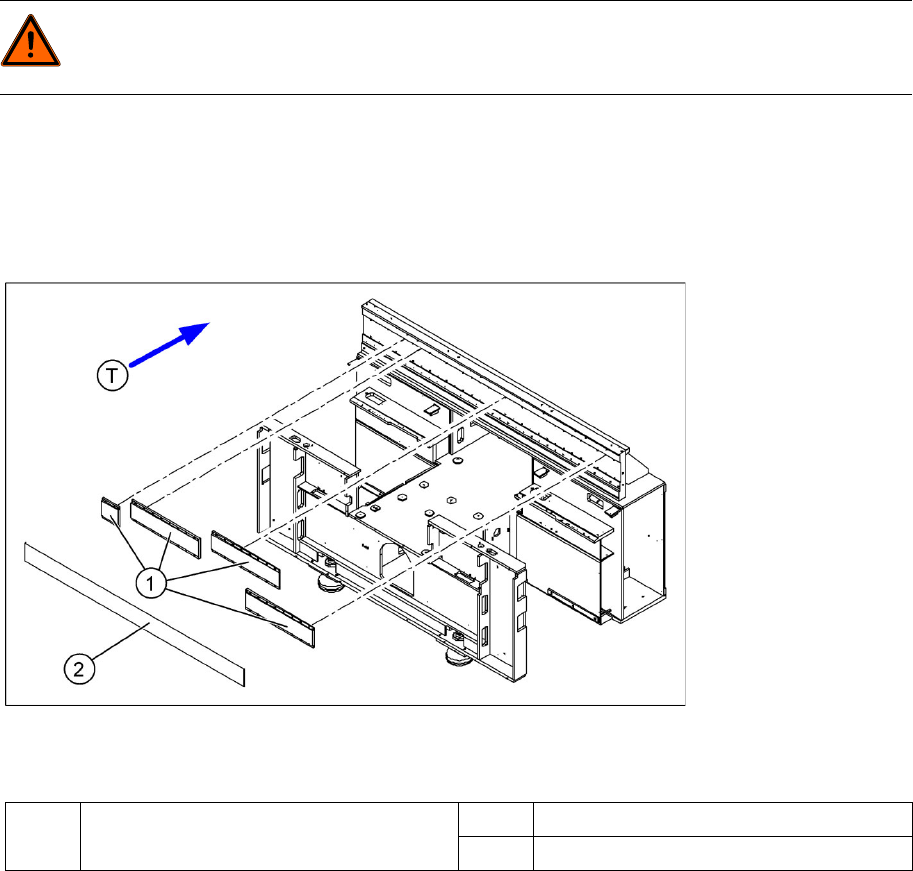
4-8: Position of the permanent magnets for the Y-axis linear drives
Legend
DANGER: POWERFUL MAGNETIC FIELD
Always follow the special safety instructions when working in the vicinity of powerful magnetic
fields.
1 Permanent magnets for Y linear drive of
gantries 1 and 2
2 Cover plate for permanent magnets
T Transport direction
Service Work
Gantry D1/D2
32 Servicemanual (internal version) SIPLACE D Series
X Remove the blue supports. Remove the magnet cover to do this.
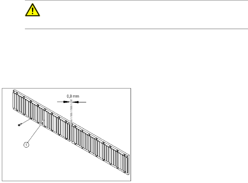
X Loosen the 8 or 16 M6 x 14 hexagon socket-head screws of the permanent magnet (1).
X Lift the permanent magnet and place it on a clean, nonmagnetic surface (such as a plank of wood).
X Move the gantry to a position which gives you good access and pull the magnet cover out from under
the Y motor.
Installation
Settings
X Check the axis dynamics of the drives removed.
CAUTION: Permanent magnets
When permanent magnets are placed on a magnetic surface (e.g. iron, nickel or steel), be
extremely careful not to catch your hands or fingers between the surface and the permanent
magnet. If you do, you will not be able to lift the magnet from the surface on your own.
X Fit the permanent magnets (4 or 16 M6 x 12
hexagon socket-head screws). The space at
the bottom must be 0.8 mm. Use the
appropriate feeler gauge or plastic strip to help
you. A gap of approx. 0.8 mm should be
between the magnet plates.
X Fit the cover strips on the crossbeam above
the gantry concerned (3 M6 x 8 hexagon
socket-head screws).