SIPLACE D系列Servicemanual.pdf - 第65页
Service Work D3 Gantry Servicemanual (internal version) SIPLACE D Series 65 X With the aid of a 1/100 plastic thic kness gauge, check the gap be tween the portal contact edge and the guide trolley (1 ) . The gantry must …
Service Work
Gantry D3
64 Servicemanual (internal version) SIPLACE D Series
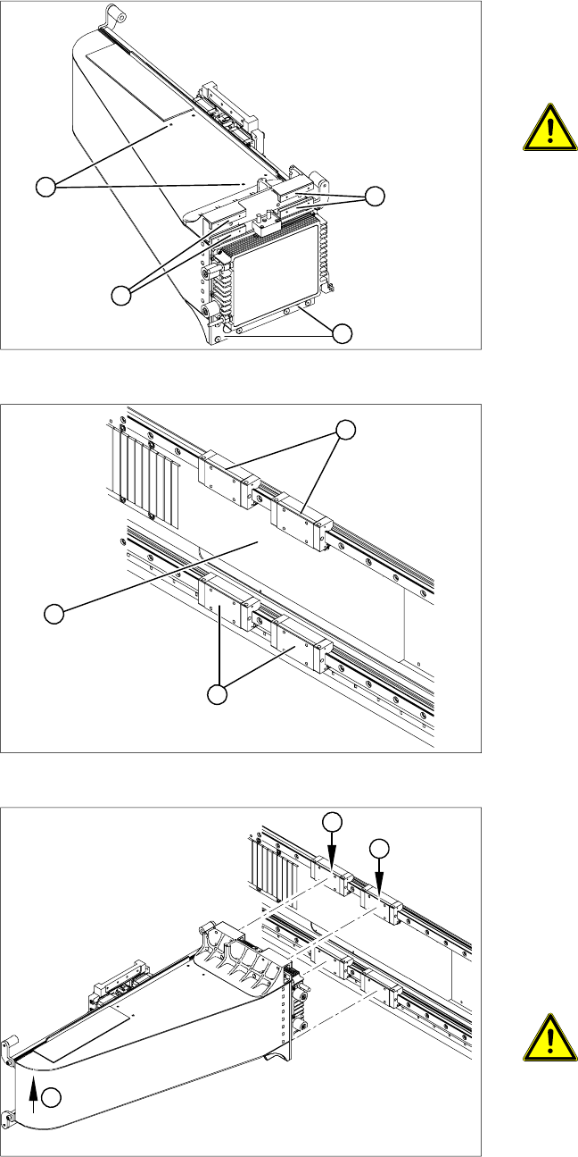
Installation
X Check whether the holes (4 x M3) for the
trailing cable pressure plates (1) on the new
gantry have been properly drilled through. If
not, re-cut the thread with an M3 screw tap.
CAUTION:
Take care not to damage the surface of
the gantry during drilling.
X Carefully rub the contact surfaces (2) on the
new gantry with a dressing stone (oil stone)
and wipe clean with a cloth and ethanol.
2
2
1
2
X Carefully rub the following contact surfaces
with a dressing stone (oil stone) and wipe
clean with a cloth and ethanol.
Legend
1. Magnet support
2. Contact surfaces of the 4 guide trolleys
3. Contact edges of the 4 guide trolleys
X Enlist the help of a second strong person. Lift
the gantry up to the guide trolleys and secure
the gantry at the top with two screws (M4 x 14).
Then loosely screw in the remaining screws.
Observe the correct screw lengths.
1
3
2
X Do not tighten the fastening screws yet!
X Lift the far end of the gantry (1) so that the
gantry rests on the contact edges of the top
guide trolley (2).
X Tighten the top fastening screws.
X Then tighten all 16 fastening screws with the
aid of the special torque wrench ("Bruchsal
version") (9.5 N).
ATTENTION:
If the special torque wrench is not
available, make sure that the two
bottom screws on the guide trolley are
not overtightened.
2
1
2
Service Work
D3 Gantry
Servicemanual (internal version) SIPLACE D Series
65
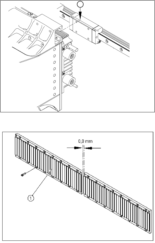
X With the aid of a 1/100 plastic thickness
gauge, check the gap between the portal
contact edge and the guide trolley (1). The
gantry must lie flush with the guide trolley,
leaving no room in-between for the thickness
gauge.
X If this is not the case, dismantle the gantry and
clean the contact surfaces again thoroughly
(with the dressing stone).
1
X Fit the magnetic strip (1).
X Make sure that there is a gap of 0.8 mm
between the two magnetic strips.
X Install the blue covers.
X Install the cover plate for the magnet.
X Install the trailing cable.
X Install the PCB camera.
X Reconnect to the electrical and pneumatic
systems.
X Fasten all electrical leads and pneumatic
hoses to the correct points.
X Install all dismantled modules, covers and
cover plates.
Service Work
Gantry D3
66 Servicemanual (internal version) SIPLACE D Series
4.1.3.6 Replacing the Y Linear Motor - Primary Part
Item number
Linear motor Y drive, complete (D3, X series) [03013459-xx]
Removal
Installation
Settings
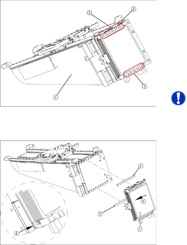
X Check the axis dynamics of the drives removed.
X Dismantle the gantry (see section (4.1.3.5 Re-
placing Gantries
J
61 ) ) and put it in a
suitable place (1).
X Remove the cable ties holding the connection
cable.
X Remove the proximity switch mount (2) and
proximity switches.
X Undo the 16 fastening screws (3). Make sure
you do not lose the insulating plates
underneath the screws. These must be
replaced after completing service work.
NOTE:
The fastening screws have been
secured with locking varnish (Loctite
241).
X Loosely fasten the new Y drive (1) with the
screws and insulating plates (2) provided. Use
Loctite 241 to secure it.
X Press the motor upwards, within the tolerance
of the drilling (3). if you do not do this, the
motor could lie on the bottom guides. Now
tighten the two center screws.
X Make sure that the ends of the insulation
plates (4) are not protruding (these plates are
not symmetrically centered). If necessary,
press these back in with a suitable tool (e.g.
screwdriver).
X Then tighten all 16 fastening screws with the
aid of a torque wrench (first in the center, then
at the top and lastly at the bottom) (5.5 N).
X Install the proximity switch mount and
proximity switches.
X Fasten the connection cable so that it will not
be in the way when installing the gantry.
X Install the gantry and the trailing cable.