SIPLACE D系列Servicemanual.pdf - 第64页
Service Wo rk Gantry D3 64 Servicemanual (internal ve rsion) SIPLACE D Series Installation X Check whether the holes (4 x M3 ) for the trailing cable pressure plates (1 ) on the new gantry have been pro perly drilled thr…
Service Work
D3 Gantry
Servicemanual (internal version) SIPLACE D Series
63
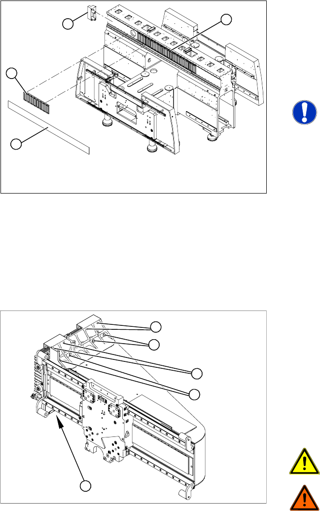
Dismantling the Magnet Cover and the Magnetic Strip
Removal
X Lift the magnet cover plate (1) at the side with
the long magnetic strip and then fix the end of
the cover plate to the X gantry with adhesive
tape. You can now access the long magnetic
strip.
X Lever up the blue covers and loosen the 16
screws fastening the long magnetic strip (4).
NOTE:
If the blue cover is damaged (kinks,
cracks etc.), replace it during
reinstallation. White or pale patches in
the plastic indicate areas of damage.
X Remove the long magnetic strip (4).
X Close the magnet cover plate and fix it to the
machine base.
X Remove the bumper (3) from the side with the
long magnetic strip (4).
X Push the gantry over the magnet cover plate
and out of the magnetic strip's area of
influence.
1
4
3
2
Legend
1. 8 fastening screws at the top (M6 x 14)
2. 8 fastening screws at the bottom (M6 x 22)
X First remove 14 of the 16 screws (6 from the
top and 8 from the bottom).
X Please note that the screws are of different
lengths. Mark the positions of each screw to
ensure that they are correctly replaced after
service work.
CAUTION:
The gantry is heavy (approx. 37 kg).
DANGER:
Please take special care when working
in the vicinity of the powerful magnetic
fields produced by the X axis magnetic
strip. Risk of serious injuries through
trapped limbs.
X Enlist the help of a second strong person.
X Stand firmly next to the gantry and hold it with
both hands, while the other person removes
the remaining two screws.
X Lift the gantry off the guide trolley and carry it
out of the machine.
1
1
1
1
2
Service Work
Gantry D3
64 Servicemanual (internal version) SIPLACE D Series
Installation
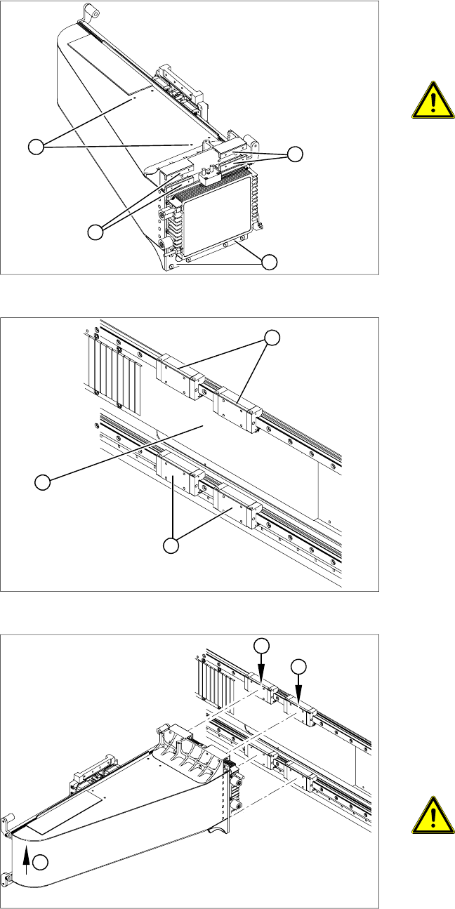
X Check whether the holes (4 x M3) for the
trailing cable pressure plates (1) on the new
gantry have been properly drilled through. If
not, re-cut the thread with an M3 screw tap.
CAUTION:
Take care not to damage the surface of
the gantry during drilling.
X Carefully rub the contact surfaces (2) on the
new gantry with a dressing stone (oil stone)
and wipe clean with a cloth and ethanol.
2
2
1
2
X Carefully rub the following contact surfaces
with a dressing stone (oil stone) and wipe
clean with a cloth and ethanol.
Legend
1. Magnet support
2. Contact surfaces of the 4 guide trolleys
3. Contact edges of the 4 guide trolleys
X Enlist the help of a second strong person. Lift
the gantry up to the guide trolleys and secure
the gantry at the top with two screws (M4 x 14).
Then loosely screw in the remaining screws.
Observe the correct screw lengths.
1
3
2
X Do not tighten the fastening screws yet!
X Lift the far end of the gantry (1) so that the
gantry rests on the contact edges of the top
guide trolley (2).
X Tighten the top fastening screws.
X Then tighten all 16 fastening screws with the
aid of the special torque wrench ("Bruchsal
version") (9.5 N).
ATTENTION:
If the special torque wrench is not
available, make sure that the two
bottom screws on the guide trolley are
not overtightened.
2
1
2
Service Work
D3 Gantry
Servicemanual (internal version) SIPLACE D Series
65
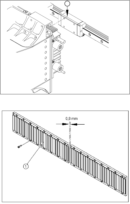
X With the aid of a 1/100 plastic thickness
gauge, check the gap between the portal
contact edge and the guide trolley (1). The
gantry must lie flush with the guide trolley,
leaving no room in-between for the thickness
gauge.
X If this is not the case, dismantle the gantry and
clean the contact surfaces again thoroughly
(with the dressing stone).
1
X Fit the magnetic strip (1).
X Make sure that there is a gap of 0.8 mm
between the two magnetic strips.
X Install the blue covers.
X Install the cover plate for the magnet.
X Install the trailing cable.
X Install the PCB camera.
X Reconnect to the electrical and pneumatic
systems.
X Fasten all electrical leads and pneumatic
hoses to the correct points.
X Install all dismantled modules, covers and
cover plates.