SIPLACE D系列Servicemanual.pdf - 第74页
Service Wo rk Gantry D4 74 Servicemanual (internal ve rsion) SIPLACE D Series 4.1.4 D4 4.1.4.1 Replacing th e X Axis Scale [00329316-01] Tools and Equipment Set of DIN 911 Allen keys Spacer gauge SITEST program Par…
Service Work
D3 Gantry
Servicemanual (internal version) SIPLACE D Series
73
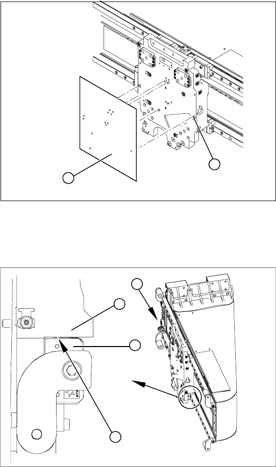
Installation Check for Guide Trolley and Motor Support
Installation check
X Clean all drillings with a pipe cleaner and
ethanol, to remove any adhesive residues.
X Position the relevant template on the centering
pins of the head mount and attach the
template.
X Use the holes in the template to screw the grub
screws (with Loctite 241) into the head mount.
X These grub screws must be level with the
surface of the head mount (countersunk).
1
2
X Shine a nonmagnetic xenon flashlight, from
behind, to check between the X drive and
magnetic strip (1).
X Between the motor support (2) and the guide
trolley (3) you should not be able to see a gap
(4).
X If you can see a gap, remove the X drive and
fit it again.
X Check the gap between the X drive and the
magnet cover with a 0.4mm thickness gauge.
X To do this, place the thickness gauge between
the X drive and the magnet cover and then
push the X drive back and forth along the
entire length. Make sure none of the parts jam.
4
1
3
2
Service Work
Gantry D4
74 Servicemanual (internal version) SIPLACE D Series
4.1.4 D4
4.1.4.1 Replacing the X Axis Scale [00329316-01]
Tools and Equipment
Set of DIN 911 Allen keys
Spacer gauge
SITEST program
Parts
X-axis scale for D4 [00329316-01]
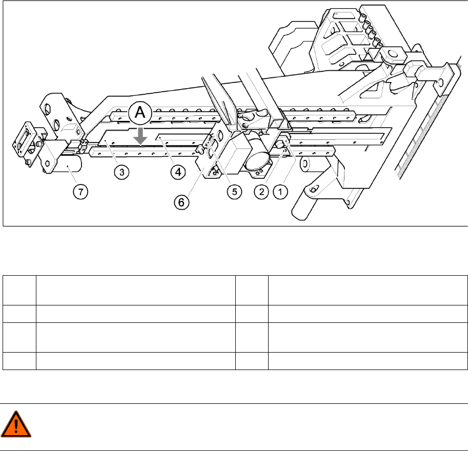
Removing the X-axis scale
4-18: Removing the X-axis scale (HS)
Legend
X Switch off the machine and secure it to prevent unauthorized reactivation.
X Dismantle the X axis incremental encoder (1). To do this, loosen the two M3x8 hexagon socket-head
screws (2).
X Loosen the 11 M 2.5x5 hexagon socket-head screws (3) with washers.
X Move the head mount (6) as far as the elastomeric spring (7).
X Remove the scale (4).
1 Incremental encoder, X-axis 5 X-axis proximity switches B1 and B2 (no longer
present since axis controller A364)
2 2 x M3x8 hexagon socket-head screws 6 Head mount
3 11 x M2.5x5 hexagon socket-head screws with
washers
7 Elastomeric spring
4 Scale, X-axis A Stop for the scale on the bars
DANGER:
POWERFUL MAGNETIC FIELD
X Always follow the special safety instructions when working in the vicinity of powerful magnetic
fields.

Service Work
D4 Gantry
Servicemanual (internal version) SIPLACE D Series
75
Installing the X-axis scale
X Carefully insert the scale.
X Loosely tighten the eleven M2.5 x 5 hexagon socket-head screws with washers.
X Push the scale along the bars as far as the stop.
X Tighten the M2.5 x 5 hexagon socket-head screws equally on both sides, starting from the center of
the scale.
X Loosely fasten the X-axis incremental encoder with the two M3x8 hexagon socket-head screws.
X Use the feeler gauge to set the 0.4 mm gap between the incremental encoder and scale.
X Now tighten the two hexagon socket-head screws.
Settings
X Set and calibrate the C&P head and gantry axes using the SITEST program.
CAUTION:
X Do not touch the incremental tracks with bare fingers.