SIPLACE D系列Servicemanual.pdf - 第97页
Service Work Replacing the Twin Head Hoses Placement H eads Servicemanual (internal version) SIPLACE D Series 97 X Move the short h ose between the elbow and the rotary supply. The rotary supply and the Z axis must b e c…
Service Work
Placement Heads Replacing the Twin Head Hoses
96 Servicemanual (internal version) SIPLACE D Series
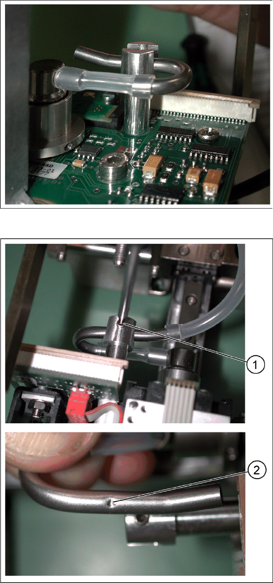
X Place the elbow into its holder.
X Fix the elbow loosely with the fastening screw
(1).
Carefully move the elbow, so that the screw
engages with the notch (2) .
Service Work
Replacing the Twin Head Hoses Placement Heads
Servicemanual (internal version) SIPLACE D Series
97
X Move the short hose between the elbow and
the rotary supply.
The rotary supply and the Z axis must be
centered in their guidance (1) .
Press the hose onto the connection or away
from it, until the axis is positioned in the center.
An eccentric position of the Z axis can alter the
balance of forces and lead to placement
errors.
The short hose must also run horizontally (2)
between the elbow and the rotary supply.
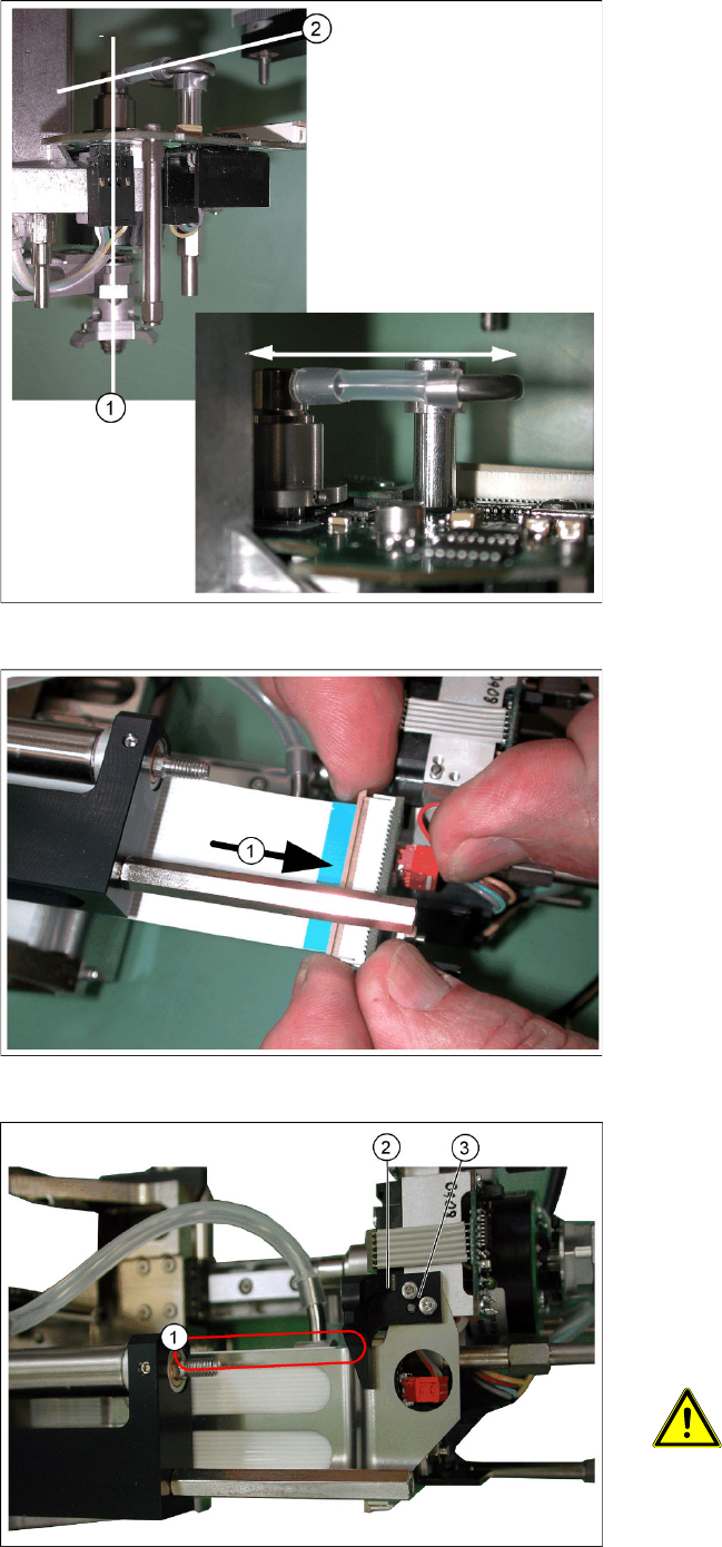
X After successfully adjustment, tighten the
screw fastening the elbow.
X Reconnect the long hose at the top.
X Reconnect the flat ribbon cable connector (1).
X Place the flat ribbon baffle on the flat ribbon
cable.
X Place the return unit stopper (2) onto the flat
ribbon baffle.
X Insert the two screws (3) into the stopper.
X Align the flat ribbon baffle to the flat ribbon
cable.
ATTENTION:
The baffle and cable must run parallel
to one another (1)!
Service Work
Placement Heads Replacing the Twin Head Hoses
98 Servicemanual (internal version) SIPLACE D Series
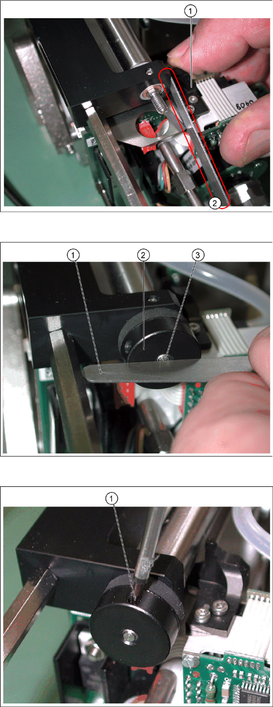
X Move the Z axis upwards.
X Insert the feeler gauge 0.6 mm (2) next to the
stopper (1).
X Tighten the screws fastening the stopper.
X Extract the feeler gauge.
X Screw the bumper (2) in until the underside is
level with the screw (3) (checked with the
feeler gauge (1) on the photo).
X Fix the bumper with the side screw (1).