SIPLACE D系列Servicemanual.pdf - 第72页
Service Wo rk Gantry D3 72 Servicemanual (internal ve rsion) SIPLACE D Series Installation Closing drillings for individual head config urations The drillings used to fast en the head vary be tween the different head con…
Service Work
D3 Gantry
Servicemanual (internal version) SIPLACE D Series
71
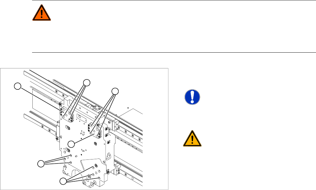
DANGER: Risk of fatal injuries through trapped limbs.
Place a piece of foam between the X drive and the magnetic strip for safety purposes.
For additional safety, keep the 4 dismantling screws in place until the X drive has been removed
from the machine.
X Once the X drive is out of the vicinity of the strong magnetic field, it can be removed from the
machine. Loosen the 4 lock screws to remove it.
X Now loosen the 12 remaining fastening screws
(1).
NOTE: Note the screw lengths!
Make a note of the different screw
lengths. These will need to be correctly
replaced later. Mark the positions of the
individual screws.
WARNING:
Do not undo or loosen the screws on
the Z axis compensation (2), which
have been secured with locking
varnish.
X Screw in the dismantling screws in
turn, so that the X drive is evenly
pushed away from the magnetic field
of the magnetic strip. The X drive is
now held by the 4 lock screws.
1
1
1
2
2
M4 x 8
M4 x 18
M4 x 14
1
Service Work
Gantry D3
72 Servicemanual (internal version) SIPLACE D Series
Installation
Closing drillings for individual head configurations
The drillings used to fasten the head vary between the different head configurations. Those which are
not needed must be closed. This prevents the cooling air from escaping!!
Template for 12/6 C+P head (03011690-xx)
Template for Twin Head (03011693-xx)
Grub screws M 4x6-ST (00309422-xx)
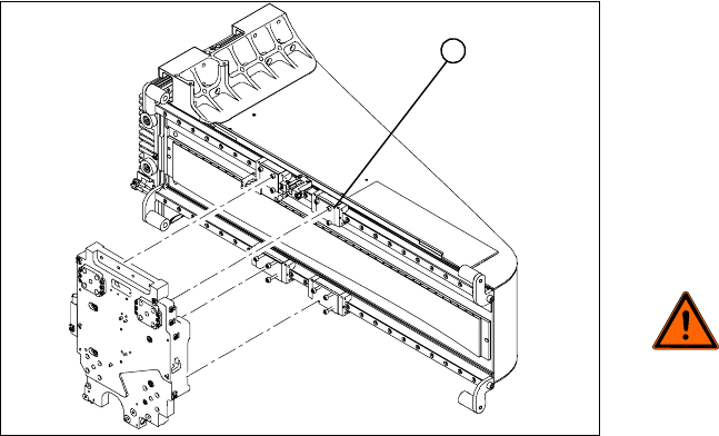
X Clean the contact surface of the guide trolley
(1) with a dressing stone (oil stone). Then wipe
the contact surface clean with ethanol.
X Screw the dismantling screws fully into each
side of the new X drive.
X Place the foam rest on the magnetic strip.
X Lift the new X drive up to the guide trolley and
fasten the X drive with the M4x60 lock screws.
X Remove the foam rest.
DANGER: Risk of fatal injuries
through trapped limbs.
Make sure that you do not trap any
limbs between the X drive and the
magnetic strip.
X Now fit 3 fastening screws on each side.
Observe the different screw lengths.
X Remove the lock screws and fit the fastening
screws in their place.
X Tighten all fastening screws crosswise with a
torque wrench (2.9 N).
X Install the PCB camera.
X Check the gap between the X drive and the
magnet cover with a 0.4mm thickness gauge.
X To do this, place the thickness gauge between
the X drive and the magnet cover and then
push the X drive back and forth along the
entire length. Make sure none of the parts jam.
1
Service Work
D3 Gantry
Servicemanual (internal version) SIPLACE D Series
73
Installation Check for Guide Trolley and Motor Support
Installation check
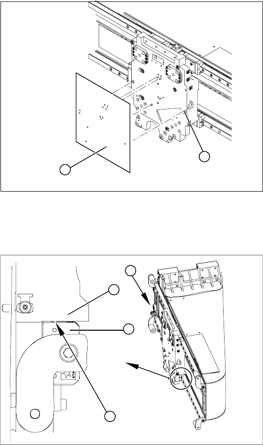
X Clean all drillings with a pipe cleaner and
ethanol, to remove any adhesive residues.
X Position the relevant template on the centering
pins of the head mount and attach the
template.
X Use the holes in the template to screw the grub
screws (with Loctite 241) into the head mount.
X These grub screws must be level with the
surface of the head mount (countersunk).
1
2
X Shine a nonmagnetic xenon flashlight, from
behind, to check between the X drive and
magnetic strip (1).
X Between the motor support (2) and the guide
trolley (3) you should not be able to see a gap
(4).
X If you can see a gap, remove the X drive and
fit it again.
X Check the gap between the X drive and the
magnet cover with a 0.4mm thickness gauge.
X To do this, place the thickness gauge between
the X drive and the magnet cover and then
push the X drive back and forth along the
entire length. Make sure none of the parts jam.
4
1
3
2