00196624-04_Service Manual WPC5_6_EN_01-2019.pdf - 第105页
Service Manua l WPC5 / WPC6 Page 3-105 3.7.15 Sensor 17 NSM (WPC6) – Safety Sensor loading flap Spare Part • Safety sensor loading f lap [03056989- xx] Removal / Install ation ➢ Remove the cover on t he load unit (see …
Service Manual WPC5 / WPC6
Page 3-104
➢ Fit the cover back on the loading unit and screw tight.
See also...
@
3.5.2
Replace the Load Axis Drive Motor [➙ 3-34]
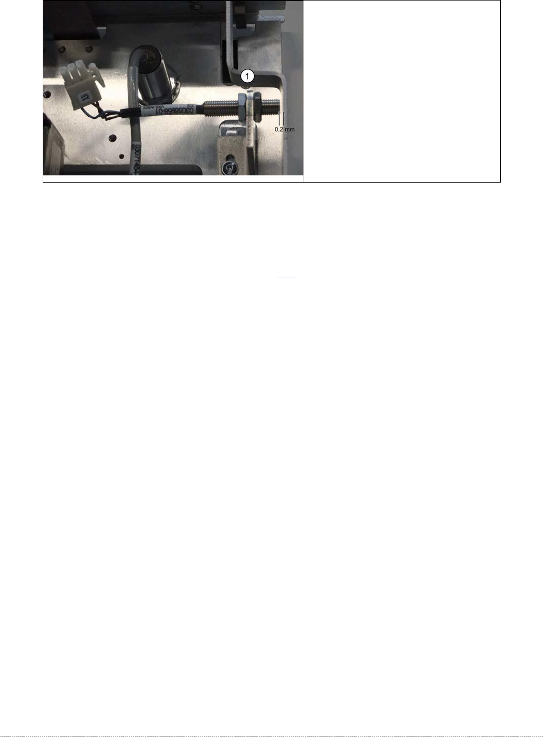
➢ Unscrew the sensor (1) from its
mount.
➢ Screw the sensor into its mount.
➢ Use a feeler gauge to set the
distance between the safety flap
and the sensor to 0.2 mm.
➢ Reconnect connector X3 to the
circuit board.
Service Manual WPC5 / WPC6
Page 3-105
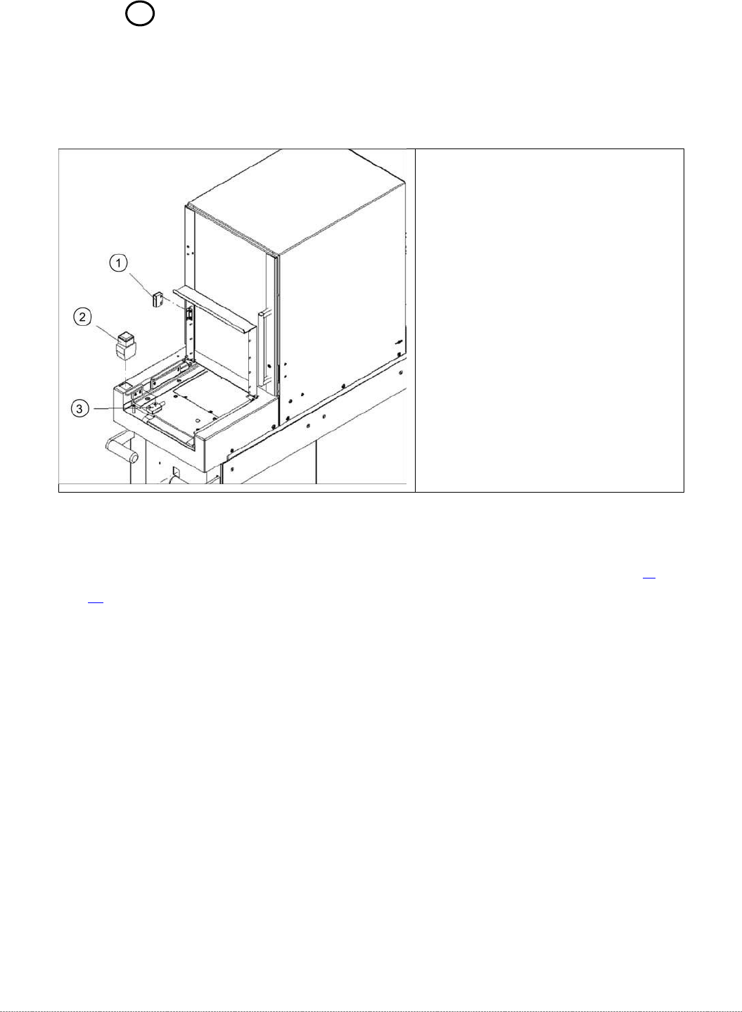
3.7.15 Sensor 17 NSM (WPC6) – Safety Sensor loading flap
Spare Part
• Safety sensor loading flap [03056989-xx]
Removal / Installation
➢ Remove the cover on the load unit (see "3.5.1.1 Remove the Cover on the Load Unit" [➙ 3-
32]).
➢ Open the loading flap.
➢ Disconnect the cable x2j from the sensor and unthread it.
➢ Remove the two fastening screws and then take off the sensor.
➢ Insert the new sensor and fix into place with the two screws.
➢ Thread the sensor cable into place again and reconnect it.
➢
Fit the cover back on the loading unit.
Legend
1. Actuator BPS 260-2
2. Button with signal light
3. Safety sensor loading flap
Service Manual WPC5 / WPC6
Page 3-106
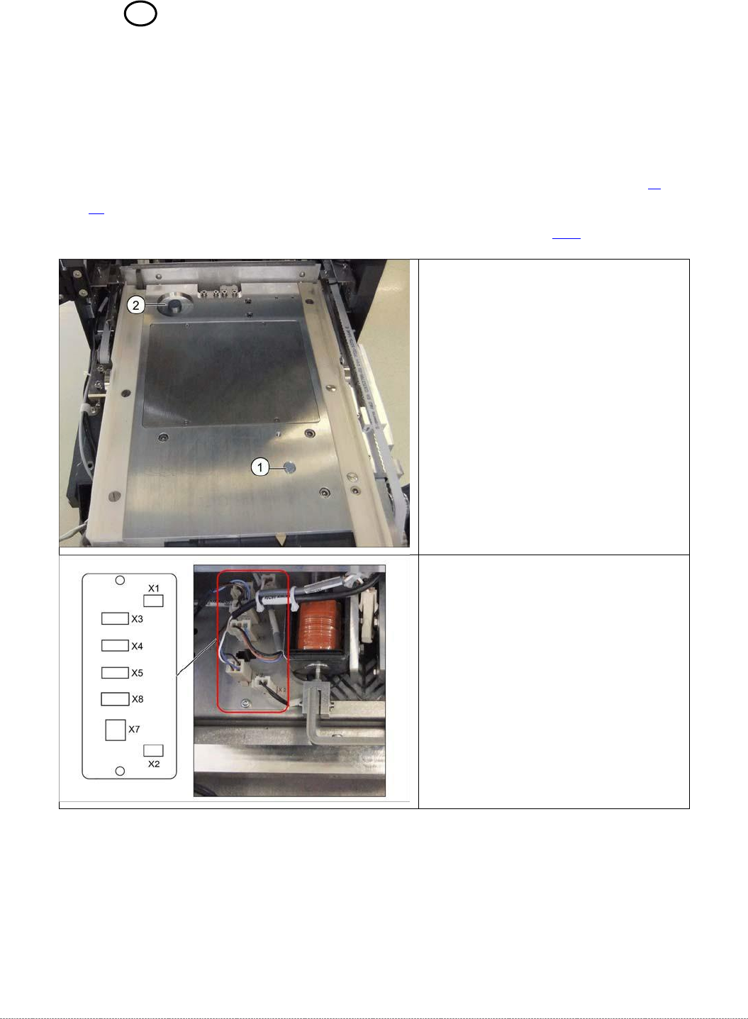
3.7.16 Sensor 14 NSM module (WPC6) – Tray detection sensor
Spare Parts
• Sensor Tray detection load axis [03056989-xx]
Removal / Installation
➢ Remove the cover on the load unit (see "3.5.1.1 Remove the Cover on the Load Unit" [➙
3-
32]).
➢ Dismantle the lifting magnets (see "3.5.4 Replace the Lifting Magnets" [➙ 3-39]).
Legend
1. Sensor tray correctly inserted
2. Sensor tray detection load axis
➢ Disconnect connector X5 from the
circuit board.