00196624-04_Service Manual WPC5_6_EN_01-2019.pdf - 第128页
Service Manua l WPC5 / WPC6 Page 4-128 4.2.4 Calibrating the Limit Switch The p lus an d min us pos ition o f the limit s witc hes nee d to b e cali brate d. Calibrating the limi t switch - ➢ Select the feed ax is (1).…
Service Manual WPC5 / WPC6
Page 4-127
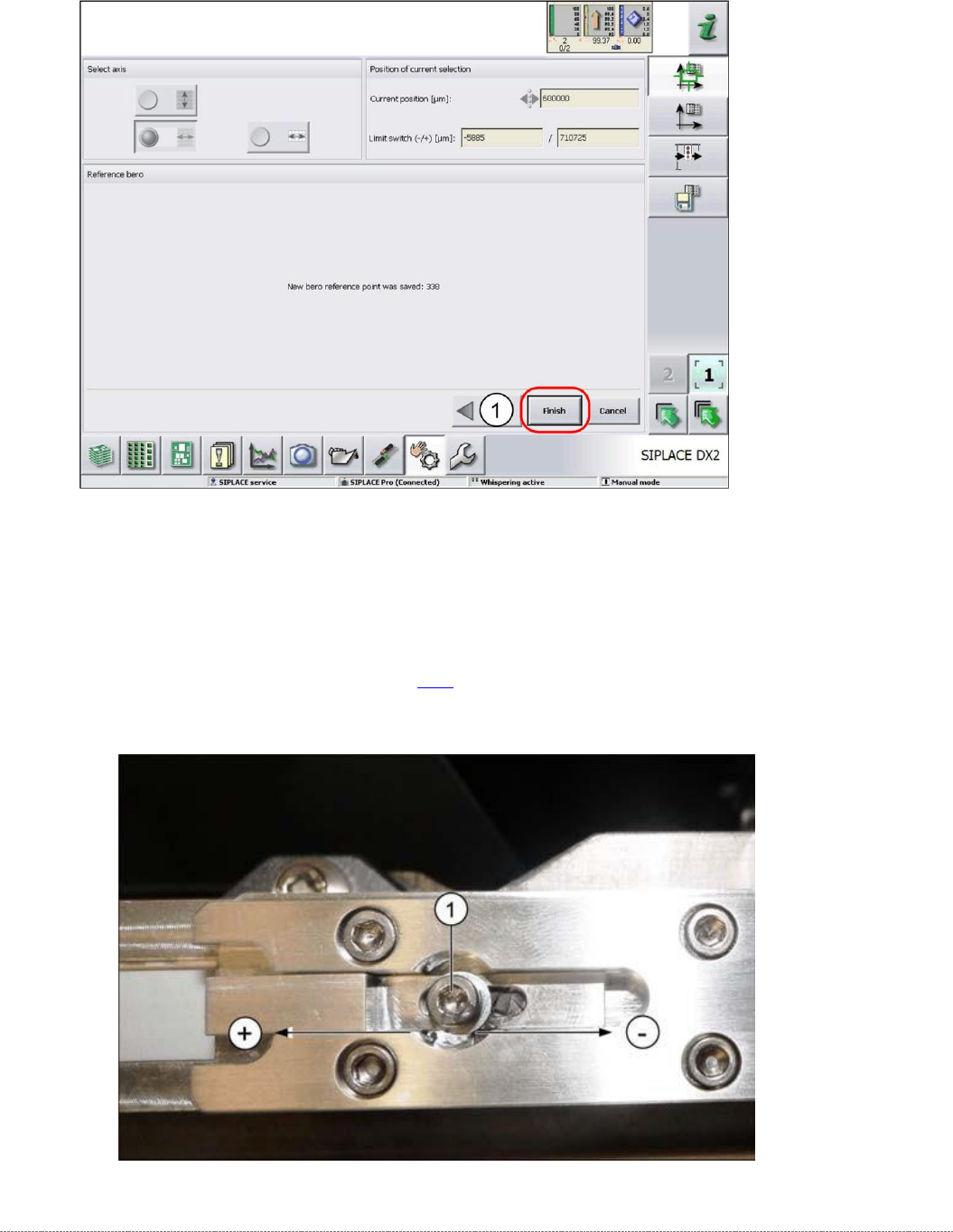
➢ Confirm the new reference point proximity switch with
Finish
(1).
Setting the Driver Cam
➢ Loosen the screw (1), fastening the cam to the driver.
➢ Correct the position of the cam by moving it accordingly in either the – or + direction.
➢ Retighten the screw (1) and repeat the measuring steps (see "3.7.5 Replace the Reference
Sensor, Feed Axis [03057837-xx]" [➙ 3-79]).
➢ Repeat the individual steps until no more error messages appear.
Service Manual WPC5 / WPC6
Page 4-128
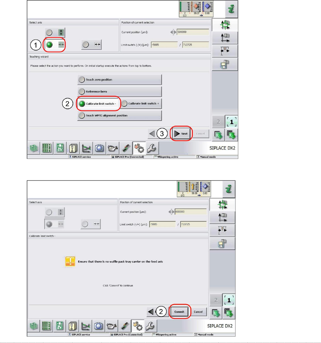
4.2.4 Calibrating the Limit Switch
The plus and minus position of the limit switches need to be calibrated.
Calibrating the limit switch -
➢ Select the feed axis (1).
➢ Select the function
Calibrate limit switch -
(2).
➢ Select
Next
(3).
➢ Follow the instruction shown and continue with
Commit
(1).
Service Manual WPC5 / WPC6
Page 4-129
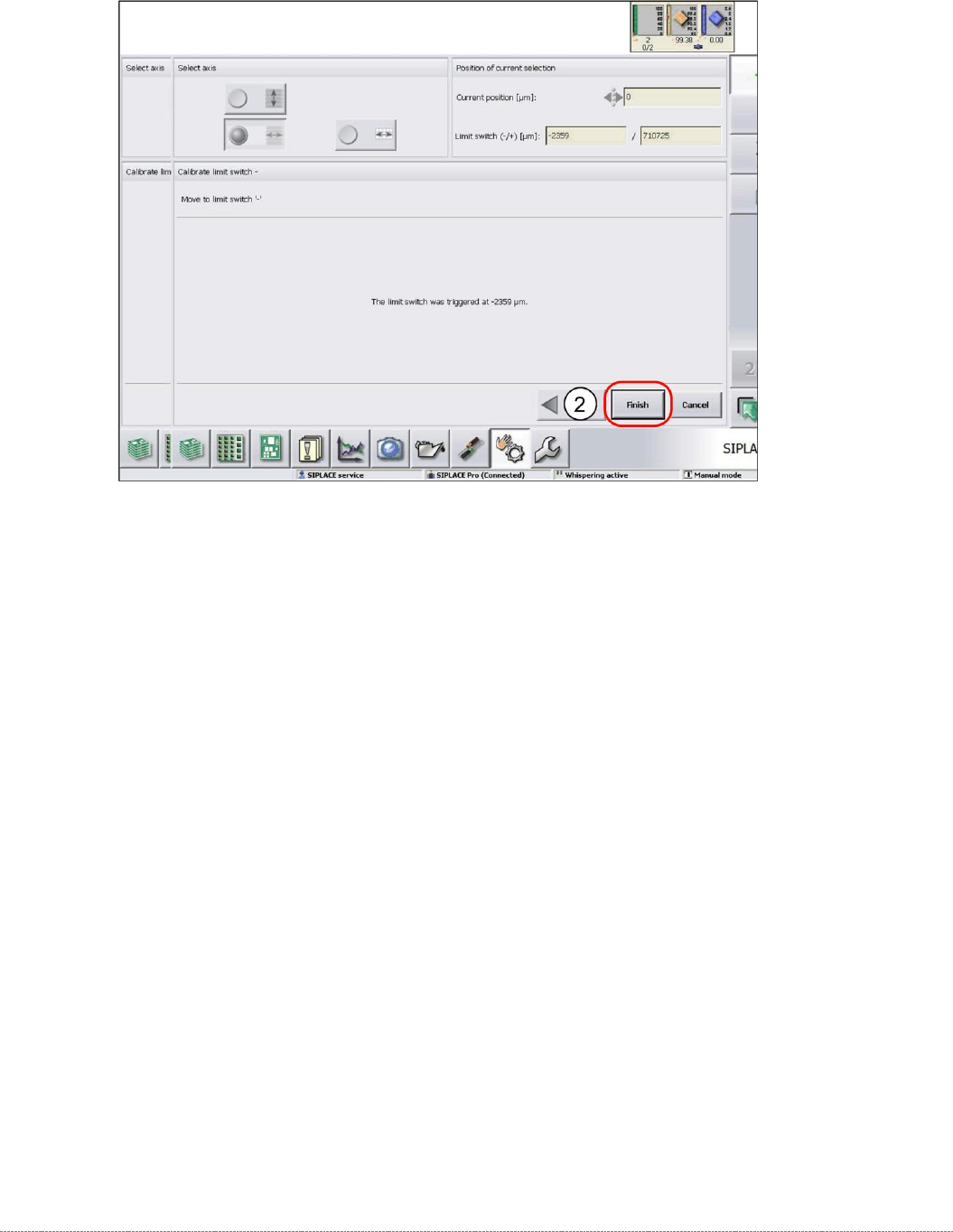
➢ Confirm the new position at which the limit switch triggers with
Finish
(1).
Calibrating the limit switch +
➢ Select the feed axis (1).
➢ Select the function
Calibrate limit switch +
and continue with the same procedure as that
used for calibrating the limit switch.