00193733-02.pdf - 第46页
1 Montageanleitung LP-Kamera Multicolor SIPLACE F5 HM SIPLACE F5 HM 1.13 Anhang: Platinen, Kabel und Schaltpläne Ausgabe 05/2007 46
SIPLACE F5 HM 1 Montageanleitung LP-Kamera Multicolor SIPLACE F5 HM
Ausgabe 05/2007 1.13 Anhang: Platinen, Kabel und Schaltpläne
45
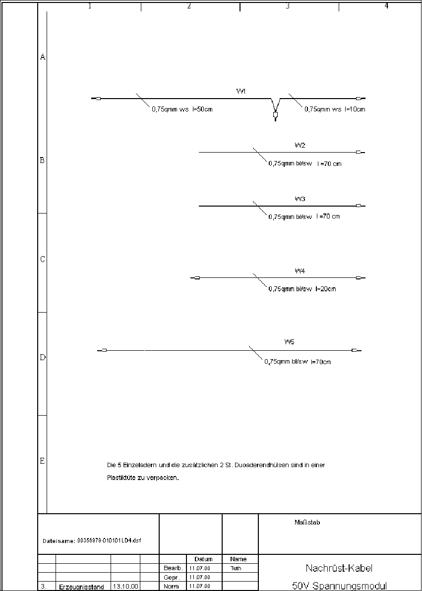
Abb. 1.13.7 Montagesatz Kabel für 24V/50 V Spannungsmodul
1 Montageanleitung LP-Kamera Multicolor SIPLACE F5 HM SIPLACE F5 HM
1.13 Anhang: Platinen, Kabel und Schaltpläne Ausgabe 05/2007
46

SIPLACE F5 HM 2 Assembly Instructions PCB Camera, Multicolor SIPLACE F5 HM
05/2007 Edition 2.1 Overview
47
2 Assembly Instructions PCB Camera,
Multicolor SIPLACE F5 HM
2.1 Overview
These instructions describe how to assemble the optional "PCB Camera Multicolor" on SIPLACE
F5 HM.
The optional PCB camera Multicolor is used in place of the subgantry camera (PCB camera with
normal light) AND the optional oblique illumination. It is utilized to improve the recognition of fidu-
cials (reference marks) and therefore to achieve greater accuracy during placement.
With the PCB camera Multicolor it is possible to acquire at least the entire range of fiducials cur-
rently recognizable with normal or oblique illumination.
Only the Siemens SMD service engineer is authorized to carry out the assembly.
The PCB camera Multicolor is only to be operated after it has been properly installed (see
Abschn. 2.2.2).
– Software version 407.01 or later is a requirement.
– On machines manufactured from Sep 98 to Dec 98 a DIN mounting rail (top-hat rail) has to
be installed on the RH side of the terminal panel. This rail is not included in the assembly
kit. For details, see Section 2.4.4.1.
– Following approximate values are intended to help you ascertain the total time required:
- 0.5 hr. per placement head for exchanging the PCB camera
- 1.0 hr. per machine for wiring.
- 0.5 hr. for configuration at the line computer and in the SITEST and setting of the illu-
mination on the station.
- 2.0 hr. to calibrate placement head, IC head and cameras via SITEST.
NOTE
It is only necessary to use the "new" head cover (with bulge or - as a preliminary solution - a cutout
for the IC camera 16 x 16) if the FC camera 16 x 16 is on or is being installed on the 6-segment
revolver head (SP 6). For this reason the new head cover is included in the assembly kit of the
FC camera 16 x 16.
Without FC camera 16 x 16, the old head cover can be re-used if the cables of PCB camera Mul-
ticolor have been run as described here. 2